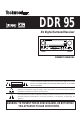
DDR 95 AV Digital Surround Receiver FUNCTION ION VOLUME E DIGITAL STANDBY COAXI AL OPTICAL COAXIAL OPTIC AL MUTING G 1 2 3 BAND FM MODE DE MODE MEMORY SLEEP MUTING G TAPE 2 MONITOR OR BASS BOOST OFF BASS POWER R STANDBY/ON /ON PHONE S PHONES SPEAKERS ERS A TEST TONE SPEAK ER SPEAKER CONFIG G LEVEL SELECT SELEC T ADJUST TREBLE LE VIDEO DELAY TIME CENTER R ON BALANCE NCE L AUDIO R REAR B L R OWNER’S MANUAL CAUTION RISK OF ELECTRIC SHOCK DO NOT OPEN CAUTION: TO REDUCE THE
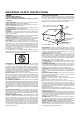
IMPORTANT SAFETY INSTRUCTIONS CAUTION: • Read all of these instructions. • Save these instructions for later use.
CONTENTS PRECAUTIONS . . . . . . . . . . . . . . . . . . . . . . . . . . . . . . . . . . . . . . . . . . . . . . . . . . . . . . . . . . . . . . . . . . . . . . . . . . . . . . . . . . . . . . . . 4 CONNECTIONS Audio Connections . . . . . . . . . . . . . . . . . . . . . . . . . . . . . . . . . . . . . . . . . . . . . . . . . . . . . . . . . . . . . . . . . . . . . . . . . . . . . . . . . 5 Video Connections . . . . . . . . . . . . . . . . . . . . . . . . . . . . . . . . . . . . . . . . . . . . . . . . . . .
PRECAUTIONS Read This Before Operating TO THE USER This equipment has been tested and found to comply with the limits for a A/V receiver, pursuant to Part 15 of the FCC Rules. These limits are designed to provide reasonable protection against interference in a residential area. This device generates and uses radio frequency energy and if not installed and used in accordance with the instructions, it may cause interference to radio or TV reception.
CONNECTIONS Audio connection cords CAUTION : Do not plug the power cord of any component into AC outlets and do not turn their POWER switches on until all connections have been performed. The cable connectors should be fully inserted into the jacks. Loose connections may cause hum and noise. Read the instructions for each component you intend to use with the receiver. To make these connections, use interconnect cords with RCA plugs.
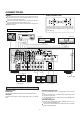
CONNECTIONS S-VIDEO signal jacks Connecting Video Equipment AUDIO signal jacks Connect the video deck (VCR) LINE output (AUDIO OUT) jacks to the IN (VCR/VIDEO 1) jacks, and the video deck (VCR) LINE input (AUDIO IN) jacks to the OUT (VCR/VIDEO 1) jacks. Connect the TV AUDIO OUTPUT jacks to the VIDEO 2 IN jacks. VCR/VIDEO 1 Video Deck (VCR) AUDIO OUT VIDEO OUT TV AUDIO OUT VIDEO IN AUDIO IN Connect the TV monitor S-VIDEO IN jack to the MONITOR OUT jack.
Notes : If a speaker is connected directly to the PRE OUT jack without an amplifier connected, no sound comes from the speaker. Subwoofer speakers are optional and are not required. Connecting the PRE OUT jacks This unit is equipped with Subwoofer and Center PREOUT jacks. These jacks allow connection off an optional powered subwoofer and connection of the center channel output to specially equipped TV’s that will play the center channel through the TV speakers.
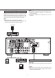
CONNECTIONS VIDEO CONNECTIONS FM Outdoor Antenna VIDEO AUDIO L AUDIO R In an area where FM signals are weak, it will be necessary to use a 75-ohm unbalanced-type outdoor FM antenna using the provided matching transformer, as shown. Generally, a 3-element antenna will be sufficient; if you live in an area where the FM signals are particularly weak, it may be necessary to use one with 5 or more elements. Connect the coaxial cable of the antenna to the matching transformer as shown.
AM Antenna Connecting Speaker Systems Caution : To avoid damaging the speakers by inputting a sudden high-level signal, be sure to switch the power off before connecting the speakers. AM Indoor Loop Antenna A high-performance AM loop antenna provided with the receiver is sufficient for good reception in most areas. Connect the loop antenna’s wires to the AM antenna terminals as shown. Place the antenna on a shelf, for example, or hang it on a window frame, etc.
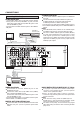
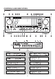
CONTROLS AND INDICATORS Front Panel 28 2 14 1 28 4 5 32 33 34 24 7 33 8 22 11 FUNCTION VOLUME DIGIT ANDBY COAXIAL OPTICAL MUTING BAND FM MODE MODE MEMOR SLEEP MUTING APE 2 MONIT BASS BOOST BASS POWER ANDBY/ON 1 PHONES SPEAKERS 13 17 TEST 16 3 18 SPEAKER CONFIG LEVEL SELECT ADJUST 19 20 21 DELA CENTER Example: BALANCE VIDEO AUDIO REAR 23 Example: - 10 - TREBLE TIME 15 10 9 25 12
Remote control Unit FRONT Panel and REMOTE 1 2 3 4 5 6 7 8 1 9 VCR VIDEO 1 TV VIDEO 2 AUX VIDEO 3 DVD VIDEO 4 MD TAPE 1 TAPE 2 MONITOR CD TUNER 10 11 2 12 PHONO 13 14 15 6 16 17 MEMORY SCAN 26 27 DIRECT TUNING BAND PRESET CALL REC/PAUSE PAUSE TAPE SEARCH R.PLAY STOP F.PLAY SEARCH PAUSE STOP PLAY/ PAUSE 18 9 7 31 19 20 21 22 23 30 34 32 18 29 SKIP SURROUND ON/OFF MODE 3 DISC SKIP REPEAT 1/ALL A-B R.LEVEL OSD ON/OFF TEST TONE C.LEVEL SUB W. ON/OFF C.
AUDIO OPERATIONS Basic Operations Note : The following points apply throughout the “AUDIO and VIDEO OPERATIONS” sections unless otherwise noted. To simplify explanations, instructions refer to names of buttons and controls on the front panel, making no mention of the use of remote control unit. To listen to a source other than TAPE 2 (tape deck), press the TAPE 2 MONITOR button to the OFF position (the TAPE M monitor indicator will not light in the display).
Audio Adjustments SURROUND Mode MASTER VOLUME MUTE BALANCE FUNCTION (Source) Selector DIGITAL INPUT SURROUND ON/OFF SPEAKERS POWER (STANDBY/ON) BASS/TREBLE (Tone controls) SURROUND MODE Button The Surround mode changes whenever you press this button. For digital equipment : CD, TV/ VIDEO 2, AUX/ VIDEO 3, DVD/VIDEO 4. (when selected digital 1, 2 or 3 input.) BASS BOOST POWER STANDBY/ON Button Press STANDBY/ON button to turn the power on. Press it again to turn the system off (power standby mode).
AUDIO OPERATIONS Radio Reception Manual Tuning Auto Tuning FM MODE FM MODE POWER ON POWER ON Manual Tuning is generally used to tune to stations broadcasting a signal that is too weak to be received by Auto Tuning. 1. Select the TUNER mode by turning the FUNCTION selector. 1. Select the TUNER mode by turning the FUNCTION selector. 2. Select AM or FM by pressing the BAND selector button. 2. Select AM or FM by pressing the BAND selector button. 3. Press the MODE button to change to TUNING mode.
Direct Tuning Tuning Using this method, the required frequency is input directly, using the numeric keys on the remote control unit. This feature is used to store FM, AM broadcasting from Channel 1 to 30 respectively. You can set 30 AM and 30 FM stations in memory. Automatic Memory Presetting VCR VIDEO 1 TV VIDEO 2 AUX VIDEO 3 DVD VIDEO 4 MD TAPE 1 TAPE 2 MONITOR CD TUNER MEMORY SCAN DIRECT TUNING BAND PHONO PRESET CALL REC/PAUSE PAUSE TAPE SEARCH R.PLAY STOP F.
AUDIO OPERATIONS Manual Memory Presetting Listening to Records and Compact Discs POWER ON POWER ON Turntable or 1. Select the TUNER mode by turning the FUNCTION selector. CD Player 2. Select AM or FM by pressing the BAND selector button. 1. Select the PHONO or CD mode by turning the FUNCTION selector. 2. Play the turntable (with a moving magnet cartridge) or CD player. 3. Press the MODE button to change to TUNING mode. (The PRESET CH. indicator disappears from the display). 4.
Playing TAPE 2 Deck Dubbing from TAPE 2 to MD/TAPE 1 TAPE Indicator Lit TAPE Indicator Lit POWER ON POWER ON Recording Tape Deck 2 Tape Deck 2 Tape Deck 1 1. Set the TAPE 2 MONITOR button to ON ; the TAPE M monitor indicator will appear in the display. 1. Set the TAPE 2 MONITOR button to ON. 2. Operate tape deck (TAPE 2) for playback. 2. Turn the FUNCTION selector, and select a source (except MD/TAPE 1). 3. Start playback on the tape deck (TAPE 2). Recording a Source 4.
VIDEO OPERATIONS Playing Video Sources Recording with a Video Deck Note : For playing video software using a certain Surround Effect function, refer to the SURROUND EFFECTS section. Tape Dubbing (from TV/VIDEO 2, AUX/VIDEO 3 or DVD/VIDEO 4 to VCR/VIDEO 1) TAPE 2 MONITOR OFF Video signals Audio signals Video signals Audio signals POWER ON TV/VIDEO 2 POWER ON VCR/VIDEO 1 VCR/VIDEO 1 TV/VIDEO 2 DVD/VIDEO 4 AUX/VIDEO 3 DVD/VIDEO 4 AUX/VIDEO 3 1.
SURROUND EFFECTS When you use the surround function, the sound creates a “live” atmosphere such as that experienced in movie theaters, disco, stadium and concert halls. DOLBY PRO LOGIC Use this mode when playing movie or music video software which carries the DOLBY SURROUND mark. This mode provides the effect of being in a movie theater or live concert house-an effect with an intensity which can only be obtained through DOLBY PRO LOGIC SURROUND.
SURROUND EFFECTS Speaker Positioning Speaker Configuration This installation positions of speakers differ according to the size, and acoustics of the listening room. While actually listening to a program source, try various speaker positions to determine which layout provides the best surround effect. Speaker layout example when using SURROUND MODE Front Speakers POWER ON Center Speaker Subwoofer It is important to perform speaker configuration prior to using the decoder.
b. When in Dolby PRO LOGIC Mode, Choose from: Front Speaker : LARGE Center Speaker : LARGE Rear Speaker : LARGE SMALL SMALL SMALL Channel Level NONE c. When in 3 Stereo Mode, Choose from: Front Speaker : LARGE SMALL Center Speaker : LARGE SMALL SUBWOOFER output - SUB-ON : Choose if a subwoofer is used. Low frequencies of 90Hz and below in the LFE channel and other selected channels are output to the subwoofer. - SUB-OFF : Choose if no subwoofer is used.
BACK-UP SYSTEM SURROUND EFFECTS Playing Surround Sound Back-up Memory Function This function stores the preset memory and most-recent memory functions. In the event of a power failure, or if the power cord of this unit is disconnected from the electric outlet, the back-up memory will save the preset memory and most-recent memory functions for approximately 3 days. If the power supply is interrupted for 3 days or longer, the memory settings will be erased. POWER ON When to Use RESET Function 1.
OSD (ON SCREEN DISPLAY) 2) When the OSD ON/OFF button on the remote control is pressed, a display appears which shows the current status of the input being monitored: When your Techwood AV Digital Surround Receiver is connected to a television, you can operate the unit with the remote control by making selections from on-screen menus. If a menu remains on the screen for a period of time without a selection being made, the display will disappear. Most menus disappear after 20 seconds.
OSD (ON SCREEN DISPLAY) 4) Entering INPUT SELECTOR from the MAIN MENU brings up a display that allows you to select the video input that you'd like to monitor. Move the arrow using the up/down buttons, then change the input source with the left/right buttons located on either side of the ENTER button. SURROUND ON/OFF MODE R.LEVEL OSD ON/OFF TEST TONE C.LEVEL SUB W. ON/OFF C.LEVEL NIGHT MODE DIGITAL INPUT R.LEVEL DELAY CENTER REAR An asterisk (*) appears opposite the input currently selected.
When you are monitoring ANALOG input, use the left/right buttons to select one of these SURROUND MODE choices: When you are monitoring PHONO, TUNER, MD/TAPE 1, or VCR/VIDEO 1, use the left/right buttons to select one of these SURROUND MODE choices: SURROUND ON/OFF MODE R.LEVEL OSD ON/OFF SURROUND ON/OFF MODE R.LEVEL OSD ON/OFF TEST TONE C.LEVEL SUB W. ON/OFF C.LEVEL SUB W. LEVEL TEST TONE C.LEVEL SUB W. ON/OFF C.LEVEL NIGHT MODE DIGITAL INPUT R.
OSD (ON SCREEN DISPLAY) Your choices will vary according to the SURROUND MODE you are using. Use the up/down buttons to move the arrow and the right/left buttons to make your selections. SURROUND ON/OFF MODE R.LEVEL OSD ON/OFF TEST TONE C.LEVEL SUB W. ON/OFF C.LEVEL NIGHT MODE DIGITAL INPUT R.LEVEL DELAY CENTER REAR 8) Entering LANGUAGE from the MAIN MENU brings up a menu that allows you to change the language of the on screen menus. SUB W.
Once this display appears, pressing the CENTER or REAR DELAY TIME, or the CENTER or REAR LEVEL buttons will enable you to change the function of the button pressed using the right/left buttons. Pressing SUB W ON/OFF or SUB W LEVEL will allow you to change the sub-woofer setting by pressing the same button a second time. Without input, the display will disappear in 7 seconds.
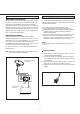
REMOTE CONTROL UNIT Using the Remote Control Unit Battery Installation By using the provided remote control unit, the receiver and some other components including DVDC96, DVDC 95, CDC 86, CDC 85 and TDX 85 can be controlled from your listening position. To use the remote control unit, point it at the REMOTE SENSOR window of the receiver (or other component). REMOTE SENSOR window of the receiver or other component 1. Remove the battery compartment cover. 2. Insert two “AAA” (R03, UM-4) dry batteries.
TROUBLESHOOTING To determine any problem with your receiver, always check the most obvious possible causes first. If any problem still remains after your have checked the items below, consult your nearest TECHWOOD dealer. Problem Probable Cause Remedy Amplifier When listening to the music in stereo, left/right speakers sounds reversed. Speakers are connected wrong. After checking, if needed, reconnect. Low hum or buzzer sound. Power line of a fluorescent light is installed near this product.
SPECIFICATIONS Amplifier Section FM Tuner Section Output Power (Front) : F.T.C. Rating: 130 watts RMS per channel minimum, both channels driven into 8 ohms from 20 Hz to 20 kHz with no more than 0.09% total harmonic distortion (U.S.A./Canada model) Surround Output Power (0.5% THD, 1 kHz, 8 ohms): 100 + 100 Watt (Front) 100 Watt (Center) 100 + 100 Watt (Rear) Total Harmonic Distortion (Front) : 0.
WELTON U.S.A. 11625 COLUMBIA CENTER DR.