Uninterruptible Power Supply EVO DSP TT 10-100kVA User’s manual
Important Notice Thank you for purchasing TECNOWARE UPS. This document provides instructions about safety, installation and handling of the UPS. It is necessary to read the manual completely before working on this equipment. Read the manual completely before working on this equipment! Keep this manual near UPS for easy consultation! Symbols This symbol points out the instructions which are especially important.
Index 1 Safety .......................................................................................................... 4 2 Installation .................................................................................................... 5 2.1 2.2 2.3 2.4 Transportation ............................................................................................. Unpacking................................................................................................... Storage ........................
8 Communication Interfaces ............................................................................... 28 8.1 8.2 8.3 8.4 9 RS232 Communication ................................................................................... 28 RS422 Communication ................................................................................... 28 Digital Inputs (UPS OFF and GEN ON).................................................................. 29 Free Contact Communication....................................
1 Safety Information related to the safety of the UPS, loads and the user is summarized below. But the equipment should not be installed before reading this manual completely. The equipment may only be installed and commissioned by authorized technical persons. When the UPS is brought from a cold place to a warmer place, humidity in the air may cause condensation in the UPS. In this case, allow UPS to stand for two hours in the warmer place before beginning with the installation.
2 Installation 2.1 Transportation The UPS must remain in a vertical position throughout the transportation. Make sure that the floor can support the weight of the system – check with building engineer if not sure. 2.2 Unpacking Equipment and batteries whose packaging is damaged during transportation shall be inspected by a qualified technical person before starting with the installation. The procedure is as follows: Remove the bands and the protective packaging from the UPS.
Access is through the use of a tool or lock and key, or other means of security and is controlled by the authorized person responsible for the location. Recommended operating temperature, humidity and altitude values are listed on the “Technical Specifications” section. Air conditioning may be required to provide these values. Other requisites are: The equipment and the batteries shall not be exposed to direct sunlight or placed near to a heat source.
If the loads have a nonlinear characteristic, the current on the mains input, separate Bypass mains input may have a value that is 1.5-2 times the current phase value during operation. In this case, size the neutral cables and the input/output protection accordingly. According to EN 62040-1-2, the user shall place a warning label on the input distribution panel and the other primary power isolators, in order to prevent the risk of electric shock caused by a fault voltage on the UPS.
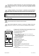
2.5.1 Internal Battery Connection The models EVO DSP TT 10-30 KVA can be equipped with internal batteries. In such case these devices may have very hazardous voltages on the Battery terminals. When the UPS has battery inside, before doing any operation please do the following points: 1 Remove the back UPS cover to access to the battery pack. 2 Connect the negative battery terminal A to the positive battery terminal B through the included cable (see the following figure).
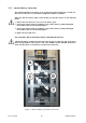
2.5.2 Power Connections The power screw terminals are located on the lower front side of the UPS. Refer to the names of each terminal to identify it during connection. Connection terminals for all standard models Connection terminals for all models with optional split Bypass Battery terminals: use only to connect external battery. Cables shall be passed through the hole under the connection terminals. Make sure that all circuit breakers are “OFF”/“0” before starting with the installation.
A definite phase sequence is needed for the UPS to operate. If you encounter “INP SEQ FAIL” alarm message at start-up, stop and switch off the UPS, ensure the protection devices (breakers/isolators) on the input distribution panels are “OFF”/“0”, then interchange any two phases on the UPS input only. 2.5.2.
3 Operating Modes There are three operating modes, which differ in the path of the energy flow.
When UPS has no separate Bypass mains input, Bypass line is also fed from the mains input. Thus, if such a device is in question, mains input shall be comprehended when the Bypass mains input is referred in the following sections of the manual. UPS behavior at the start-up is different from the usual operation. The UPS can only operate in Bypass mode during start-up.
3.2 Normal Mode Energy is drawn from the mains input. Loads are fed via the Rectifier and the Inverter. The AC voltage at the input is converted to a DC voltage by the Rectifier. The Inverter converts this DC voltage to an AC voltage with a stable sinusoidal waveform, amplitude and frequency. Output voltage is sinusoidal and has a regulated amplitude and frequency. It is independent from the input voltage.
4 Control and Monitoring 4.1 Front Panel The front panel located on the upper part of the UPS informs the user about operating status, alarm conditions and measurements. It also provides access to controls and configuration parameters. Front panel shown below consists of three parts: 1. Mimic panel provides basic information about the energy flow path and existing alarms; 2. LCD (liquid crystal display) offers detailed information and provides access to controls; 3.
4.1.2 Mimic Panel Mimic panel is a diagram, which shows the path of energy flow in the UPS by means of several LED’s. Definitions of LED status are shown below: LED's ID COLOR DEFINITION STATE Input mains voltage is OK and Rectifier is active. Steady Input mains voltage is OK and Rectifier is inactive. Line 1 Line 2 Green Green Input mains voltage is very close to its upper/lower limit and Rectifier is active. Flashing Input mains voltage is not OK. Off Bypass voltage is OK.
4.1.3 Liquid Crystal Display (LCD) and User Menu LCD provides detailed information about device status, alarms and measurements. It also enables the operator to manage the UPS. All information, commands and configuration parameters are given in a menu, which has the following structure: ALR ALARMS ST MEASUREMENTS PRIORITY COMMANDS START B.
ALARMS” TABLE CODE NAME DEFINITION A01 BYP BADSHAPE Bypass mains voltage is different than the Inverter reference signal (e.g. its frequency is beyond synchronization limits or it has a Total Harmonic Distortion > %10). A02 BYP VOL HIGH Bypass mains voltage is higher than its upper limit. A03 BYP VOL LOW Bypass mains voltage is lower higher than its lower limit.
“MEASUREMENTS” MENU MEASUREMENT DEFINITION LD = XXX,XXX,XXX % Ratio of the actual Inverter active power of each line to its nominal value. Vsc = XXX,XXX,XXX V Output line/neutral voltages. Isc = XXX,XXX,XXX A Output line currents. Fo = XX.X Hz Frequency of output Line/Neutral voltages. Vby = XXX,XXX,XXX V Bypass Line/Neutral voltages. Vin = XXX,XXX,XXX V Input Line/Neutral voltages. Iin = XXX,XXX,XXX A Input line Currents. Fin = XX.
“CONFIGURATION” MENU DATE = "dd-mm-yyyy" Shows system date in dd-mm-yyyy format (dd = day, mm = month, yyyy = year). Use ENTER, UP and DOWN keys to change the date. TIME = "hh:mm:ss" Shows system time in hh-mm-ss format (hh = hour, mm = minutes, ss = seconds) Use ENTER, UP and DOWN keys to change the time. “EVENTS” MENU EVENTS (xxx) Shows last 380 events (alarms) of system. The total number of stored events is xxx. To look stored events, you must press ENTER key and then use UP/DOWN keys.
5 Operating Procedures This chapter defines the operating procedures to be followed to activate, deactivate and manage the UPS. The instructions shall be applied in the sequence in which they are written only – do not alter or miss a step – to do so may cause a fault or failure. 5.1 Commissioning 1 Make the connections according to the “Installation” section. 2 Switch the circuit breaker on the Input distribution panel to “ON”/“1” position.
5.3 Switching into Manual Bypass during Operation Manual Bypass enables the user to isolate the electronic circuitry of the UPS from the mains and the load without interrupting the load operation by connecting the loads directly to the Bypass supply. This feature is useful while performing maintenance or service and shall only be executed by authorized technical service personnel.
6 Operating Procedures for Parallel System 6.1 Introduction EVO DSP TT UPS are designed according to high MTBF figures with increased reliability but in case of necessity, a second (or more) EVO DSP TT UPSs can be connected in parallel redundant configuration for supplying the very critical load to increase reliability. Maximum of 4pcs of identical power and specification EVO DSP TT can be connected in parallel.
Figure - Communication cables connections between Parallel UPSs Do not remove the communication cables between the UPSs during parallel operation.
In case this communication cable is removed or damaged during parallel operation and the communication is lost, then the slave UPS which can not communicate with the master UPS and it shall disconnect its output and maintain the OFF condition. The other UPSs shall continue their normal operation. In such a case, this UPS should be turned off completely in order to insert its communication cable again and then switched on again. Do not try to insert the communication cable while it is operating.
9 After completing the configuration of the name of each UPS and N value, switch on the Input circuit breaker (F1), then Bypass circuit breaker (F4) (if the UPS is split Bypass version) and Inrush circuit breaker (F6) respectively on each Parallel UPS. After seeing “NORMAL” message on the LCD panel, Battery circuit breaker (F5) can be switched on. Then the Output circuit breaker (F2) can be switched on accordingly.
7 Features and Operating Limits 7.1 Mains Limits for Normal mode Frequency and RMS value of the mains input voltage has to be within acceptable limits for the UPS to operate in Normal mode. Lower limit of the voltage depends on how much the UPS is loaded and it decreases as the load decreases until it reaches 80 VAC Line-Neutral. Frequency lower and upper limits and voltage upper limit are fixed.
7.4 Overload Behavior While operating in Normal or Battery mode, the UPS can feed overloads for a limited duration which is given in the “Technical Specifications” section. After that duration, UPS automatically switches into Bypass mode, if the Bypass is enabled and frequency/waveform/RMS value of the Bypass mains voltage is within limits. If the Overload situation continues in the Bypass operation, thermal/magnetic protection devices may activate and protect the circuit.
8 Communication Interfaces All related terminals are on the Communication Interface board (A1). Connector layout is as following: 8.1 RS232 Communication DSUB-9 female connector with the following pin layout shall be used on the UPS side of the connection cable. Pin layout is given below: RS232 PIN LAYOUT Pin # Signal Name Signal Description 2 RX Receive data 3 TX Transmit data 5 GND Signal ground RS232 cable shall be shielded and shorter than 15 m.
8.3 Digital Inputs (UPS OFF and GEN ON) Voltage to be applied to the digital inputs is 5 VDC. Maximum current drawn by each input is 1 mA. 5V connector provided on the Communication Interface board can be used to supply both digital inputs. Pay attention to the polarity of the voltages applied to the digital input terminals. Input Function UPS OFF If the UPS OFF input is set high by applying 5 VDC voltage on the related terminals, UPS stops generating the output voltage and stops feeding the load.
9 Maintenance Batteries, fans and capacitors shall be replaced at the end of their lives. Hazardous voltage and high temperature metal parts inside even if the UPS is disconnected. Contact may cause electric shock and burns. All operations except replacing Battery fuses shall be carried out by the authorized technical personnel only. Some parts inside the UPS (terminals, EMC filters and measurement circuits) are still energized during maintenance Bypass operation.
10 Troubleshooting This section gives information about the procedures which shall be performed in case of abnormal operation. If you fail to fix the problem consult authorized Technical Service with the following information: Model and serial number of the UPS, which can be found on the nameplate on the rear of the UPS. This information is also available in the test report provided with the UPS. ALR and ST codes in the “ALARMS” menu.
Alarm Possible Cause Action to solve The UPS may not start up yet. This alarm is permanent if the UPS is intended to be started with the Bypass blocked or when the Bypass mains is not in specified limits. VSEC NOT OK The UPS may have stopped to feed the load because the combination of the mains conditions and the user preferences made from the “COMMANDS” menu does not allow the UPS to work in any of the operating modes (e.g.
Alarm Possible Cause Action to solve VDC NOT OK Any of the DC bus voltages approaches its lower/upper limits. Charge the batteries, and check if the alarm May mean that the batteries have has removed. approached to their lower voltage limit and are almost empty. T-AMB HIGH Ambient temperature exceeds its upper limit. GENSET ON “Generator Friendly” operation is activated (digital input “GEN ON” is set high). Check the "GEN ON" input.
11 Technical Specifications EVO DSP TT MODELS Rating [kVA] 10 15 20 30 40 60 80 100 ENVIRONMENTAL Storage temperature range Operating temperature range -25°C to +55°C (15°C - 40°C recommended for longer battery life) Relative humidity range 0% - 95% (non condensing) 0°C to +40°C (20°C - 25°C recommended for longer battery life) Max.
Static Bypass 3 Phases + Neutral Number of phases Voltage range (Line-Neutral) [V] *(Note 1) Frequency range [Hz] *(Note 1) 220 / 230 / 240 ± 10% (Line-Neutral) 47-53 Nominal power [kVA] 10 15 20 30 40 60 80 100 Nominal current [A] 15.2 22.7 30.3 45.5 60.
12 Internal Battery Location - Connection Instructions 1) Take out all the drawers outside of the UPS. 2) Place the batteries of the drawer-1 vertically as shown in the drawing of next page. Make the cable link connections between 1st battery to 7th battery. Then connect the 20 cm cable to the positive pole of the 1st battery. Insert the drawer to the upper shelf and place it on the left side where the poles of the batteries face inside as shown in the diagram.
13 Internal Battery Location - Connection Diagram Internal Battery Location is available at the UPSs from 10kVA to 30kVA.
User’s manual 38 UPS EVO DSP TT
TECNOWARE S.r.l. www.tecnoware.