
Performance Data Sheet
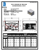

Unit BOM 32L1451-2E Fan Motor 810F050C20
Unit MODEL AWA9512ZXNHN Replacement Fan Motor 50W230 32Lxxxx-2ER(F)ATnD
Fan Motor Qty 2 R Heated/Insulated Receiver
Refrigeration Range -10°F to 45°F Fan Motor RLA 0.7 F Fixed Fan Control
Design Pressure Low / High 181 / 450 Fan Blade 51568-1 A Adjustable Fan Control
Volts - HZ - Ph 208-230V ~ 60HZ Fan Guard 70831 T1 Air Defrost Timer
Voltage Range 187 - 253 Shroud 70648-2 T2 Electrical Defrost Timer & Defrost
Min. Circuit Ampacity 14.91 Heater Contactor
Max. Fuse Size 25 High Pressure Switch 84095-2L D Disconnect Switch (nonfused)
Low Pressure Control 84026-2
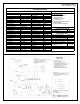
Compressor MODEL AWA9490ZXN Dual Pressure Conrol
Compressor BOM AW616ET-111-A2
Compressor LRA 52 Head Master Valve 70083 Solenoid Valve (supplied loose) KSVC-264
Compressor RL
A
10.64 Check Valve 56626 Hail Louver Ass
y
LLPG-201
Process Valve
OverLoad Internal Discharge Valve (Base) 56618
Replacement Kit - O/L Liquid Valve (Base) 56500-K06 Receiver Heater (R option) 92124-2
Relay 820ARR3H23 Liquid Valve (Receiver) attached Receiver Thermostat (R option) 84102-2
Replacement Kit - Relay Suction Valve (Base) 56500-K14 Fixed Fan Control (F option) 84132-1
Run Capacitor 85PR370F17 Suction Valve (Rotolock) 31531-1 Adjustable Fan Control (A option)
Run Capacitor Rating 35MFD 370V
Start Capacitor 85PS330D69 Condenser 50858-1 Defrost Timer (T1 or T2 option) 84110
Start Capacitor Rating 145-175 MFD 330V Receiver 51099-2L Defrost Heater Contactor and 91014B and
Contactor 91014B Accumulator TK00042000 Auxiliary Switch (T2 opt.) 91014-AUX
Liquid Filter 70139
Unit Drawing DGU1918-L101 Sight Glass 70084-S Disconnect (D option)
Wiring Diagram WD21-2XT2 Suction Filter 70822-5S
Wiring Diagram (A or F opt.) WD21-2AT2 CrankCase Heater 91022-1
AVAILABLE ACCESSORIES
REPLACEMENT PARTS
Parts/Specifications
STANDARD AVAILABLE OPTIONS
AWA9512ZXNHN_REV1
TPC - February 11, 2014