TECUMSEH T E C H N I C I A N ' S H A N D B O O K This manual covers the following models: VH80, VH100, HH80, HH100, HH120, OH120-180 Model numbers are located on the engine shroud. Other illustrated Tecumseh 2-Cycle Engine, 4-Cycle Engine and Transmission manuals; booklets; and wall charts are available through Tecumseh.
Contents Page CHAPTER 1. GENERAL INFORMATION ................................................................................................................................... 1 SECTION 1. ENGINE IDENTIFICATION ............................................................................................................................. 1 SECTION 2. ENGINE CARE ...............................................................................................................................................
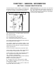
CHAPTER 1. GENERAL INFORMATION SECTION 1. ENGINE IDENTIFICATION Tecumseh engine model numbers are stamped into the blower housing, or are located on a nameplate or tag on the engine in locations as illustrated. OH160-170033 SER 8044C SHORT BLOCKS. New short blocks are identified by a tag marked SBH (Short Block Horizontal) or SBV (Short Block Vertical). Original model tags of engines should always be transferred to a short block for correct parts identification. INTERPRETATION OF MODEL NUMBER.
SECTION 2. ENGINE CARE FUELS. Use clean, fresh unleaded automotive gasoline in all Tecumseh four-cycle engines. (Leaded “regular” gasoline is an acceptable substitute.) NOTE: Do Not use gasoline containing methanol (wood alcohol). Gasoline containing a maximum of 10 ethanol or grain alcohol (sometimes called “gasohol”) may be used but requires special care when engine is unused for extended periods. See “STORAGE” instructions. ENGINE OIL, ALL FOUR CYCLE ENGINES: USE A CLEAN, HIGH QUALITY, DETERGENT OIL.
DRAINING THE FUEL SYSTEM: CAUTION: DRAIN THE FUEL INTO AN APPROVED CONTAINER OUTDOORS, AND AWAY FROM ANY OPEN FLAME OR COMBUSTION SOURCE. BE SURE THE ENGINE IS COOL. 1. Remove all gasoline from the fuel tank by running the engine until the engine stops, or by draining the fuel tank by removing the fuel line at the carburetor or fuel tank. Be careful not to damage the fuel line, fittings, or fuel tank. 2.
CHAPTER 2. AIR CLEANERS, CARBURETORS, GOVERNORS AND LINKAGE SECTION 1. AIR CLEANERS PAPER-TYPE AIR CLEANER SERVICE. Dry type paper air cleaners are utilized on all Tecumseh Large Frame engines. These air cleaners have treated paper elements with rubberlike sealing edges. These edges must seal properly to prevent dirt leakage. COVER ELEMENT POLYURETHANE-TYPE AIR CLEANER. Some Tecumseh Large Frame engines may use a polyurethane air filter in conjunction with a paper filter.
SECTION 2. GENERAL CARBURETOR INFORMATION CARBURETOR IDENTIFICATION. Tecumseh carburetors are identified by a model number and code date stamping on the carburetor as illustrated. ALTERNATE LOCATION FOR MODEL NUMBER 89 3 F 89 3 F 5 This carburetor is used on the Overhead Valve engine 12, 14, 16 & 18 horsepower.
SECTION 3. TECUMSEH CARBURETORS Following are initial carburetor adjustments to be used to start the engine. After the engine has reached operating temperature make final adjustments. Main Adjustment Screw HH80-100-120 VH100, 1-3/4 turns. Idle Adjustment Screw HH80-100-120 VH100, 1-1/4 turns The Master Parts Manual or Microfiche has a direct engine-to carburetor reference list. Further identification of the carburetor is stamped on the carburetor body as shown.
HIGH SPEED ADJUSTMENT SCREW. For service, examine the taper of the high speed adjustment screw. If the taper is damaged at the area where it seats, replace the screw and fuel bowl retainer nut as an assembly. INLET NEEDLE. The inlet needle is anchored to the float tab by a clip, to assure proper movement of the inlet needle off of the seat when the float drops. The inlet needle clip must be positioned as shown during reassembly. FUEL BOWL RETAINING NUT.
HIGH SPEED NOZZLE. The carburetor body contains a main nozzle emulsion tube pressed into the carburetor body to a predetermined depth and positioned within the venturi of the carburetor. Do not attempt to remove this main nozzle. Repositioning of this nozzle will seriously affect the metering characteristics of the carburetor and will require replacement of the entire carburetor. CARBURETOR BODY. When removing the choke and throttle shafts, check shafts and bearings in carburetor body for wear.
FLOAT ADJUSTING PROCEDURE All Tecumseh carburetors with an adjustable float require the correct float height to achieve the proper operation and easy engine starts. To check the float setting, hold the carburetor in an upside down position. Remove the bowl nut, float bowl, and "O" ring. Place an 11/64" (4.369 mm) drill bit across the top of the carburetor casting on the opposite side and parallel to the float hinge pin.
SECTION 4. WALBRO CARBURETORS HH80 - 120, VH80 - 100 WALBRO CARBURETORS. Following are initial carburetor adjustments to be used to start the engine. After the engine has reached operating temperature, make final adjustments. Main Adjustment Screw HH80, 100, 120 VH80, 100, 1-1/2 turns off seat Idle Adjustment Screw HH80, 100 120 VH80 100 1-1/4 turns off seat For proper carburetion the atmospheric vent MUST be open. Examine and clean if necessary.
Do not remove the main nozzle. If it is necessary to remove the main nozzle to aid in cleaning, discard the main nozzle and use a service replacement nozzle with an under cut in the thread area. If the nozzle removed is under cut it can be reused. This procedure must be followed to assure delivery of fuel to the idle system. UNDERCUT ANNULAR GROOVE EARLY SERVICE MAIN NOZZLE (REUSABLE) ORIGINAL MAIN NOZZLE DO NOT REUSE IF REMOVED Float settings are measured opposite the float hinge.
When assembling the float to the carburetor body, position the needle spring on the adjusting tag so that it hangs down. Hold the float spring under tension until the carburetor body will support the slight spring tension. Prior to removing the fuel bowl nut, remove the high speed adjustment needle. Use a 7/16'’ box end wrench or socket to remove the fuel bowl nut. When replacing the fuel bowl nut be sure to position the fiber gasket under the nut and tighten securely.
SECTION 5. OVERHEAD VALVE ENGINE CARBURETORS Overhead valve engines utilize Walbro carburetors. THROTTLE PLATE CHOKE LEVER THROTTLE RETURN SPRING IDLE SPEED ADJUSTMENT SCREW CHOKE SHUTTER IDLE SPEED ADJUSTMENT SCREW RETAINING SCREWS ATMOSPHERIC VENT OPENING FUEL BOWL FUEL BOWL RETAINING NUT HIGH SPEED ADJUSTMENT SCREW CARBURETOR ADJUSTMENT. Carburetor factory adjustment should not be changed. However, if required, perform the following: with engine running (Allow engine to warm up for 5 minutes).
Examine the tip of the high speed adjustment screw. If the tip of the screw is damaged, the seat, which is part of the main nozzle, is probably damaged. When replacing the screw, the nozzle should also be replaced with a service replacement nozzle only. INLET NEEDLE & SEAT. The inlet needle and seat are replaceable as an assembly. If the tip appears damaged, replace the needle and seat assembly.
ASSEMBLING SEAT, SPRING & FLOAT. Shown below is the float, hinge pin, seat and the float spring. DAMPER SPRING FIXED HIGH SPEED CARBURETOR. On carburetors of a later design the high speed screw has been replaced by a fixed speed nut. Adjustment is made only on the idle adjustment screw since the high speed setting is fixed. PIN FLOAT When assembling the float to the carburetor body, position the needle spring on the adjusting tang so that it hangs down.
SECTION 6. GOVERNORS This Governor Assembly is used on current production HH & OH Tecumseh Engines. SHAFT PRESSED TO GEAR GOVERNOR GEAR There is an oil groove on the inside of the spool to prevent oil pressure from building up under the spool. Position the governor gear and flyweight assembly on the governor gear shaft. Secure with a retaining ring. Place the governor spool on the governor gear shaft.
CYLINDER COVER GOVERNOR ADJUSTMENT FOR HORIZONTAL ENGINES GOVERNOR ROD PIVOT POINT “C” GOVERNOR SPRING MOVE TO ‘RUN’ POSITION “A” RETAINING RING “B” GOVERNOR SPOOL CONTACTS LEVER TURN CCW The governor rod is retained in the cylinder cover bushing with a retaining ring. The governor spool moves the governor rod by contacting the lever. Outward movement of the governor spool moves the governor levers and carburetor throttle to a closed position.
VERTICAL CRANKSHAFT GOVERNOR ADJUSTMENT. Move remote controls to RUN position. Loosen screw “A”. Turn plate “B” counterclockwise (ccw) and hold. ADJUSTING FIXED SPEED. The fixed speed adjusting screw is the optional position “2”. Adjust it merely by starting the engine and after loosening the lock nut turn screw in (clockwise) to increase spring tension and hold engine at higher R.P.M. and out (counterclockwise) to decrease tension on spring and allow speed to be decreased more easily.
SECTION 7. IMPULSE FUEL PUMP IMPULSE FUEL PUMP. This pump is mounted onto the carburetor inlet and has connections from the fuel supply and also a pulse line to the engine crankcase. CAUTION: IN ORDER FOR THE PUMP TO OPERATE SATISFACTORILY THE CORRECT OIL LEVEL IN THE CRANKCASE MUST BE MAINTAINED. TOO MUCH OIL WILL ADVERSELY EFFECT THE PUMPS OPERATION.
CHAPTER 3. REWIND STARTERS, ELECTRIC STARTERS, TROUBLESHOOTING AND GENERATORS SECTION 1. REWIND STARTERS REWIND STARTER DISASSEMBLY PROCEDURE 1. Clamp starter in a vise and pull rope out, and clamp pulley. 2. Untie knot in rope and remove. REASSEMBLY. Lubricate the recoil spring and center shaft with a small amount of light grease. Place the pulley over the center shaft and bottom. Insert a 1/8'’ (3.175 mm) punch or rod into the through hole in the pulley, and turn the pulley.
VISE ASSEMBLING STARTER TO ENGINE. It is important to center the starter hub containing the starter dogs in the center cup so there is equal contact on all the dogs into the teeth of the cup. Before securing the starter with the mounting screws, place the hub into the cup then pull the rope enough to cause the starter dogs to equally engage in the teeth. With the dogs securely in the cup, tighten the mounting screws to 40-60 inch pounds (4.5 - 6.8 Nm) torque.
SECTION 2. ELECTRIC STARTERS STARTER SERVICE, DISASSEMBLY AND INSPECTION. Part No. is found on identification tag. Used on large frame vertical and horizontal engines. Test and trouble shooting procedures for 12 volt starters can be found in other Sections of this chapter. 2. Disassembly. a. Remove two (2) lock nuts from thru bolts on drive end of starter. b. Grasp drive end of starter and remove from housing as an assembly. PART NO.
BRUSH CARD NEW STARTER MOUNTING SCREWS AND WASHERS BRUSH AND BRUSH SPRING (4) LOCK NUT ADJUSTING BOLT CYLINDER TERMINAL POST THRU BOLTS (2) COMMUTATOR END CAP LOCK NUTS (2) 4. Assembly a. Install drive end cap, engaging nut and gear, anti-drift spring, spring retainer, retaining ring, and dust cover to armature. Install armature into housing. b. Install brush card assembly and two (2) thru bolts so stops on bolts will secure brush card. Secure lock nuts on drive end of starter. c.
ARMATURE CHECK. If commutator bars are glazed or dirty they can be turned down in a lathe. While rotating, hold a strip of 00 sandpaper lightly on the commutator, moving it back and forth. (Do not use emery cloth). Recut grooves between commutator bars to a depth equal to the width of the insulators. 3. With a pliers or vise grip tool, grasp the throughbolts as close to the flanged end as possible (away from the threaded end), and remove the two nuts retaining the driving end cap of the starter.
SECTION 3 12 VOLT STARTER TROUBLE SHOOTING CHART PROBLEM PROBABLE CAUSE FIX Does not function Weak or dead battery Check charge and/or replace battery. Corroded battery terminals and/or electrical connections Clean terminals and/or connections. Brushes sticking Free brushes. Replace worn brushes and those that have come in contact with grease and oil. Dirty or oily commutator Clean and dress commutator. Armature binding or bent Free armature and adjust end play or replace starter.
12 VOLT STARTER TROUBLE SHOOTING CHART (Cont.) PROBLEM PROBABLE CAUSE Intermittent operation Brushes binding in holders Free up brushes. Replace worn brushes and those that have come in contact with grease and oil. Dirty or oily commutator Clean and dress commutator. Replace any brush that has come in contact with grease or oil. Loose or faulty electrical connections Correct. Open armature Replace starter. Break in electrical circuit Disconnect ignition cutoff wire at the engine. Crank engine.
CHAPTER 4. GENERAL VALVE INFORMATION, CYLINDER HEAD AND BREATHER ASSEMBLY SECTION 1. GENERAL VALVE INFORMATION Adjusting valves for 8 horsepower and larger engines (except valve-in-head engines) Intake valve gap .010, (.254 mm) exhaust valve gap .020, (.508 mm) set when engine is cold. Rotate the engine to Top Dead Center of the compression stroke, this will assure that the lifter is not raised by the compression relief pin. Valve stem ends must be ground flat when adjusting valve gap.
VALVE REMOVAL PROCEDURE FOR VALVE-INHEAD ENGINES. The following is necessary for cylinder head disassembly. REMOVAL OF ROCKER ARM HOUSING PARTS. Locate the piston at top dead center for easier access in servicing the valve train. After removing the rocker arms by removing the retaining rings, it may be necessary to loosen the locknut and back off the adjusting screw before pulling off the rocker arms.
VALVE INSTALLATION. To reinstall valves, position valve caps and spring in the valve compartment. Valve spring free length should be checked and installed so the dampening coils are located opposite the keepers. INSTALL PIN Release valve spring tension to lock cap in place. FREE LENGTH 1.885” (47.879 mm) 1/32” (.
THIS SYMBOL POINTS OUT IMPORTANT SAFETY INSTRUCTIONS WHICH IF NOT FOLLOWED COULD ENDANGER THE PERSONAL SAFETY AND/OR PROPERTY OF YOURSELF AND OTHERS. READ AND FOLLOW ALL INSTRUCTIONS. VALVE GUIDE REMOVAL AND INSTALLATION INSTRUCTION FOR VALVE-IN-HEAD ENGINES. REMOVING THE OLD VALVE GUIDES 1. Submerge the head in a pan of oil so that both guides are covered with oil. 2. Heat oil on a hot plate until the oil begins to smoke. About 15 to 20 minutes. 375° (190°C) 400° (204°C). 3.
SECTION 2. CYLINDER HEAD CYLINDER HEAD TORQUE. For 8 H.P. and larger engines (except valve-in-head engines), make sure surfaces are clean, then place new head gasket on cylinder and position head. BELLEVILLE WASHER CROWN SIDE UP FLAT WASHER Slide one belleville washer (crown toward bolt head) and one flat washer (sharp edge toward bolt head) over each bolt as shown in illustration. Insert the bolts in the head with the two shorter bolts in the position shown in the illustration.
SECTION 3. BREATHER ASSEMBLIES The Breather is a sealed assembly. If it is defective, replace the entire assembly. The rubber tube on the outside is not part of the assembly. Install the breather with the drain holes toward the base of the engine. Always use a new gasket. The retaining screws must be tight. If oil is being pumped out the breather: 1. Check for excess speed. 2. Operating at excessive angles. 3. Loose oil filler cap. 4. Worn rings. 5. Excess blow-by. 6. Breather body installed up-side down.
CHAPTER 5. PISTON AND RINGS, CONNECTING RODS AND CRANKSHAFTS SECTION 1. PISTON AND RINGS PISTON AND RING DISASSEMBLY. Always remove ridge and carbon buildup before attempting to remove the piston and ring assembly from the cylinder. Always deglaze the cylinder when replacing the piston and rings. This must be done to allow the rings to seat. Make sure surfaces are clean, then place new head gasket on cylinder and position head. RING GROOVE CHECK.
ARROWHEAD FEELER GAUGE PISTON RING MATCH MARKS RING CENTERED IN RING TRAVEL AREA INVERTED PISTON TO POSITION RING SQUARELY IN CYLINDER CHECK RING END GAP PISTON RING INSTALLATION. Only correct piston ring installation will assure full power. Carefully note the ring sequence when removing the worn rings from the piston. Note especially the ring expander, as it may be found both behind the second (compression) ring and the third (oil control) ring.
SECTION 2. CONNECTING RODS When reinstalling a used connecting rod ALWAYS use new nuts on the bolts. These locking nuts will ensure that the torque will be retained when the connecting rod is replaced. FOR ENGINE MODELS VH80 and VH100 ENGINE ROTATION The connecting rod must be installed with the match mark facing out of the cylinder, toward the P.T.O. end of the crankshaft. This will ensure the correct positioning of the oil dipper. Install as illustrated.
SECTION 3. CRANKSHAFTS CRANKPIN WEAR. Crankpins should be examined for wear, scoring, or out of-round. If any of these conditions are noted, replace the crankshaft. See specifications. Lubricate the crankpin generously before attaching the connecting rod. This will prevent damage during the initial run-in after reassembly. EXAMINE CRANKPIN FOR WEAR OR DAMAGE REPLACE IF DAMAGED Note the chamfer tooth on the crankshaft gear.
CHAPTER 6. CAMSHAFT, BEARINGS AND SEALS SECTION 1. CAMSHAFT CAMSHAFT GEAR TEETH WEAR. When servicing engines, check the camshaft at the points indicated by the asterisks in figure. Examine the gear teeth for wear and damage. See Specifications. VALVE TIMING FOR ENGINE WITH HELICAL CUT GEARS. NOTE: If a damaged gear is replaced, the mating gear should also be replaced. Example: If the camshaft is damaged and replaced, the crankshaft gear should be replaced. MECHANICAL COMPRESSION RELEASE.
SECTION 2. BEARINGS BEARING ASSEMBLY. The following figure illustrates the correct assembly of the tapered crankshaft bearings. The bearing at the flywheel end of the crankshaft seats in an adjustable bearing cup “A” in the cylinder. The bearing cup “B” supporting the P.T.O. end of the crankshaft is a press fit in the cylinder cover. Examine the bearing for wear, pitting, rust, alignment, and uneven wear of the rollers. If in doubt, replace to assure dependable trouble free service.
METHOD TWO - Cold Bearing. The crankshaft MUST be supported between the counterweights when pressing on bearings. Use a driver to direct the pressure of an arbor press onto the inner race of the bearing when installing. The bearing must be seated tight against the shoulder of the crankshaft counterweight (on magneto end). TAP CRANKSHAFT LIGHTLY TO SEAT IN PTO BEARING This method may require a great amount of force, therefore, method one should be considered first.
When the space measures .001'’ (.025 mm) to .007'’ (.178 mm) no gaskets required, or if over .007'’ and shimmed with gaskets the end result is that there shall be no crankshaft end play. Shim gaskets are available in .004/.005” (.102/.127 mm) and .005/.007” (.127/.178 mm) thickness. NOTE: If clearance between cover and cylinder is over .007'’ (.178 mm) and gasket shims are not used, damage to the cylinder cover can result.
After determining the gap between the cover and the machined surface on the cylinder, determine the shim thickness as follows to result in the required .002 - .007 (.051 - .178 mm) crankshaft end play. Example: .003'’ .076 mm - .002'’ .005'’ .051 mm .127 mm + .003'’ .076 mm .008'’ .203 mm The bearing cup should be examined for rust, pitting, scuffing, cracks or other damage.
SECTION 3. SEALS Use an oil seal protector when removing covers from crankshaft. See Chapter 11 of Mechanics Manual under “Tools”, using tool as shown. Remove the cylinder cover at either the P.T.O. or flywheel end. Drive the seal out of the cylinder cover from the inside out. Install a new seal. Use new gaskets. Use the seal protector when replacing the cover. SEAL PROTECTORL DRIVE DOWN WITH HAMMER UNTIL SEAL IS FLUSH WITH COVER Ô OIL SEAL MUST BE SQUARE IN BORE SEAL DRIVER DRIVE OIL SEAL FLUSH TO .
CHAPTER 7. DYNA-STATIC ® BALANCING SYSTEM TECUMSEH DYNA-STATIC® BALANCING SYSTEM. Dyna-Static® Tecumseh’s Balancing system for horizontal crankshaft 10, 12, 14, 16 and 18 H.P. Dyna-Static ® operates by means of a pair of counterweighted gears driven off the crankshaft to counteract the unbalance caused by the counterweights on the crankshaft. The exterior distinguishing feature of an engine equipped with a balance system is the “deep-dished” side cover.
Positioning of helical-type gears is the same as shown in the figure below. PISTON AT T.D.C. PISTON AT T.D.C. SPACER On current production models, the counterweight balancing gears are placed top and bottom of the crankshaft. The position dimension is the same as for side-by-side counterweight models. COUNTERWEIGHT FULL BOTTOM COUNTERWEIGHT SPACER FULL BOTTOM REGULAR CUT GEARS HELICAL CUT GEARS 1.7135 (43.523 mm) 1.7185 (43.
CHAPTER 8. IGNITION SYSTEMS, CHARGING SYSTEMS BATTERY SERVICE and ELECTRICAL CONTROL PANELS SECTION 1. IGNITION SYSTEMS SOLID STATE SYSTEM IGNITION SERVICE. a. General. Follow through the checks and explanations below, if everything checks ok, then replace the ignition unit. The parts of the system are: 1. 2. 3. 4. 5. b. c. d. Ignition coil. Flywheel. Ignition unit. High tension lead. Spark plug. e. Air Gap Checks. Adjust the system so that a .006/.010'’ (.152/.
f. Coil Lead on 10 Amp Alternator Systems. Remove the coil lead from the ignition unit terminal. Attach the leads from a standard ohmmeter to the lead eyelet and to ground to check series resistance of the ignition generator coil. RETAINING SCREWS 1. If resistance is below 400 ohms, replace the stator assembly which includes the coil. NOTE: The ignition generator coil cannot be replaced separately. 2. If coil resistance is above 400 ohms, replace the ignition unit.
SOLID STATE IGNITION ALTERNATOR TYPE). SYSTEM (NON- SPADE CONNECTOR FOR 20 AMP IGNITION UNIT CAUTION: Do not attempt to crank engine with the primary wire of the transformer disconnected. Also do not allow the primary wire of the transformer to be grounded or arc. A broken wire causing an open circuit to or in the transformer can also cause permanent damage. See Step 2. CHARGING COIL 1. Preliminary Tests GROUND TERMINAL Spark Test . . .Check for spark.
SECTION 2. CHARGING SYSTEMS PRECAUTIONS CAUTION: Electrical components of the 10 amp alternator system are similar to the 20 amp alternator system. Use care not to interchange electrical components; severe damage will result. A. Do not connect battery to cables in wrong polarity. This will cause regulator-rectifier damage. B. Break continuity between the regulator-rectifier unit and battery when using a remote charger on the battery.
Before performing the following tests see page 48, A through F. TEST NO. 1 (NO CHARGE TO BATTERY) NOTE: Tests must be followed in their order of listing. EXAMPLE: Test No. 1 must be completed before proceeding to Test No. 2. Replace any defective part. 10 AMP ALTERNATOR TEST B+ TERMINAL WIRE Disconnect B+ at battery lead (NOTE: Keep test to a minimum with B+ wire disconnected from the battery) and check D.C. voltage between B+ regulator lead and case: D.C. VOLTMETER LEADS 1. 2500 RPM 13.0 volts min.
TEST NO. 4 (BATTERY ALWAYS CHARGING AT HIGH RATE) Check B+ to ground voltage with D.C. voltmeter. 1. 2500 RPM: Voltage over 14.7 volts. 1. Regulator not functioning. 2. 3000 RPM: Voltage over 14.7 volts. 2. Regulator not functioning. 3. 3600 RPM: Voltage over 14.7 volts. 3. Regulator not functioning. 4. 2500 RPM: Voltage under 12.0 volts. 4. Battery charge low. Alternator and Regulator System okay. Check battery. 5. 3000 RPM: Voltage under 13 volts. 5. Battery charge low.
TEST NO. 2 (NO CHARGE TO BATTERY) Disconnect plug from regulator and test AC voltage at plug. 1. 2500 RPM: Voltage reads less than 1. Defective stator. 32 volts. 2. Over 32 Volts. 2. Defective regulator See Test No.3. 3. 3000 RPM: Voltage reads less than 3. Defective stator. 38 volts. 4. Over 38 volts. 4. Defective regulator See Test No.3. 5. 3600 RPM: Voltage reads less than 5. Defective stator. 45 volts. A.C. VOLTMETER LEADS 6. Over 45 volts 6. Defective regulator See Test No.3.
TEST NO. 4 (BATTERY ALWAYS CHARGING AT HIGH RATE) Check B+ to ground voltage with D.C. voltmeter. 1. If over 14.8 volts at 2500 RPM, 3000 RPM, and 3600 RPM. 1. Regulator is not functioning. 2. If under 14.4 volts @ 2500 RPM. @ 3000 RPM. @ 3600 RPM. 2. Battery charge low. Alternator okay, check battery. D.C. VOLTMETER TEST NO. 5 (BATTERY BOILING OR FUMING). Check B+ to ground voltage with D.C. voltmeter. 1. If over 14.8 volts. 1. Regulator not functioning. Visual check for overfilling.
SECTION 3. BATTERY SERVICE BATTERY POWER DECREASES WHILE ENGINE CRANKING POWER REQUIREMENT INCREASES WITH FALLING TEMPERATURE 100% 80°F (26oC) 100% 68% 32°F (0oC) 165% 30% 46% 0°F (-18oC) 250% -20°F (-30oC) 350% greater rating is recommended. BATTERY CONDITION. While the battery is built to satisfactorily withstand the conditions under which it will normally operate, excessive mechanical abuse leads to early failure. The following points are important to properly install a battery: 1.
Check to determine if the vent holes in the caps are open. In normal usage the battery casing may be partially covered with a white powder. Clean such areas with a solution of 1 part bicarbonate of soda to 4 parts water. Use care to prevent solution from entering battery cells. If battery terminals show corrosion, remove battery connections carefully. Do not twist or use unnecessary force to remove from battery. Brighten battery posts and connections.
Battery Condition Specific Gravity Discharged 1.110 to 1.130 No useful charge 1.140 to 1.160 25% 1.170 to 1.190 50% 1.200 to 1.220 75% 1.230 to 1.250 100% 1.260 to 1.
SECTION 4. ELECTRICAL CONTROL PANELS IGNITION CUT-OFF TOGGLE SWITCH AMMETER BROWN on ON-OFF SWITCH off BROWN HEAVY DUTY PUSH BUTTON STARTER SWITCH ELECTRICAL CONTROL PANEL SERVICE PART NO. 730155. The test procedures explained below will deal only with the control panel. Before attempting to locate an apparent defect in the control panel switches or ammeter, insure all connections between control panel, starter and battery are secure and free from corrosion and wire or insulation breaks.
To test ammeter remove right side panel. Remove brown wire from “On/Off” switch. Use a volt/ohm/ millimeter. Attach one test lead to the terminal the brown wire was removed from, attach other test lead to positive terminal of start switches. Set tester to the ampere scale and start engine. Set throttle control at full throttle and observe meter. If meter registers a charge, system is okay and meter on panel is inoperative. This test can also be made using a good ammeter.
3. With the toggle switch in the “off” position, the test light will light. 4. With the toggle switch in the “on” position, the test light will not light. 5. Position the spade connectors to the original positions. DISCONNECT FROM BATTERY ON-OFF TOGGLE SWITCH STARTER SWITCH CONTINUITY TEST. Remove wires from starter switch. Place test leads on to switch terminals. No continuity should exist (Test light should not light). Leave test leads attached; depress starter button.
TROUBLESHOOTING FOR ELECTRICAL CONTROL PANEL, SERVICE PART NO. 730155. TROUBLE Electric Starter Does Not Crank Engine PROBABLE CAUSE Check to determine if crankshaft turns freely; if not, check for binding belts, pulleys, clutches, etc. Relieve load on crankshaft. Disengage associated equipment clutches, belts or pulleys. Check battery connections for corrosion and/or breaks. Correct problem. Weak or bad battery. Replace or charge battery if less than 3/4 charged. Push button starter switch.
TROUBLESHOOTING FOR ELECTRICAL CONTROL PANEL, SERVICE PART NO. 730198. TROUBLE PROBABLE CAUSE Electric Starter Does Not Crank Engine. Check to determine if crankshaft Relieve load on crankshaft. turns freely; if not, check for Disengage associated equipment binding belts, pulleys, clutches, etc. clutches, belts or pulleys. Starter Cranks Engine But Engine Does Not Start. 60 REMEDY Check battery connections for corrosion and/or breaks. Correct problem. Weak or bad battery.
CHAPTER 9. TROUBLESHOOTING TROUBLESHOOTING Below is a list of common problems and remedies. Follow a uniform procedure to locate and eliminate the causes. Cause Remedy A. ENGINE FAILS TO START OR STARTS WITH DIFFICULTY No fuel in tank. Fill tank with clean, fresh fuel. Shut-off valve closed. Open valve Obstructed fuel line. Clean fuel screen and line. If necessary, remove and clean carburetor. Tank cap vent obstructed. Open vent in fuel tank cap. Water in fuel. Drain tank.
C. ENGINE MISSES UNDER LOAD Cause Remedy Spark plug fouled. Clean and regap spark plug. Spark plug porcelain cracked. Replace spark plug. Improper spark plug gap. Regap spark plug. Pitted magneto breaker points. Clean and dress breaker points. Replace badly pitted breaker points. Magneto breaker arm sluggish. Clean and lubricate breaker point rod and arm. Check for spring tension. Faulty condenser. Check condenser on a tester; replace if defective. Improper carburetor adjustment.
Cause Remedy Governor not properly adjusted. Adjust governor. Carburetor not properly adjusted. Adjust carburetor. Intermittent spark at spark plug. Disconnect ignition cut-off wire at the engine. Crank engine. If spark, check ignition switch, safety switch and interlock switch. If no spark, check magneto. Check wires for poor connections cuts or breaks. G. ENGINE VIBRATES EXCESSIVELY Engine not securely mounted. Tighten loose mounting bolts. Bent crankshaft. Replace crankshaft.
Cause Remedy New seal damaged upon installation. Use proper seal protector tools and methods for installing another new seal. Bent crankshaft causing seal to leak. Check crankshaft for straightness and replace if necessary. (Never straighten a bent crankshaft) Oil seal driven too far into cavity. Remove seal and replace with new seal using the correct driver tool and procedures. J. BREATHER PASSING OIL Engine speed too fast. Use tachometer to adjust correct RPM.
K. TROUBLE SHOOTING CARBURETION POINTS TO CHECK FOR CARBURETOR MALFUNCTION Trouble Correction Carburetor out of adjustment ..................................... 4-12-13-14-15-17-22 Engine will not start .................................................... 1-2-3-4-5-6-7-9-12-13 Engine will not accelerate .......................................... 3-4-12-13-14-26 Engine hunts (at idle or high speed) ......................... 4-5-9-10-11-12-13-14-22-23-26 Engine will not idle.........................
CHAPTER 10. 8 H.P. & LARGER ENGINE AND TORQUE SPECIFICATIONS ALSO VALVE-IN-HEAD SPECIFICATIONS AND TORQUES SECTION 1. CROSS REFERENCE LIST FOR TABLE OF SPECIFICATIONS Craftsman Engine Model See Model Craftsman Engine Model 143.558012 143.558022 143.558032 143.558052 143.559012 143.559022 143.559032 143.559042 143.562012 143.562022 143.562032 143.568032 143.569022 143.569032 143.569042 143.569052 143.569082 143.572012 143.572022 143.572032 143.572042 143.572052 143.572062 143.572092 143.572102 143.
Model HH80 HH100 U.S. Metric Displacement 23.7 384.4cc Stroke 2-3/4'’ Bore Timing Dimension 69.85mm U.S. HH120 Metric U.S. Metric 23.7 284.4cc 27.66 453.4 cc 2-3/4'’ 69.85mm 2-7/8'’ 73.025mm 3.3120 84.125 3.3120 84.125 3.500 88.900mm 3.3130 84.150 3.3130 84.150 3.501 88.925mm TDC-Start .095 Run TDC-Start 2.41 .095 Run TDC-Start 2.41 .095 Run 2.41mm Point Gap .020 .508 .020 .508 .020 .508 Spark Plug Gap .028 .033 .711 .838 .028 .033 .711 .838 .028 .
Model HH80 HH100 HH120 U.S. Metric U.S. Piston Pin Diameter .6873 .6875 17.457 17.463 .6873 .6875 17.457 17.463 .6873 .6875 17.457 17.463 Width Comp. Ring Groove .0950 .0960 2.413 2.438 .0950 .0960 2.413 2.438 .0950 .0960 2.413 2.438 Width Oil Ring Groove .1880 .1900 4.775 4.826 .1880 .1900 4.775 4.826 .1880 .1890 4.775 4.826 Side Clearance Ring Groove .0020 .0035 .051 .889 .0020 .0035 .051 .889 .0020 .0035 .051 .889 Ring End Gap .007 .020 .178 .508 .007 .020 .178 .
Model VH80 VH100 U.S. Metric U.S. Metric Valve Face Angle 45° 45° 45o 45o Valve Face Width .089 .099 2.261 2.515 .089 .099 2.261 2.515 Valve Lip Width .06 1.524 .06 1.524 Valve Spring Free Length 1.885 47.879 1.885 47.879 Valve Guides STD Diameter .312 .313 7.925 7.950 .312 .313 7.925 7.950 Valve Guides Over-Size Dimensions .344 .345 8.738 8.763 .344 .345 8.738 8.763 Diameter Crankshaft Conn. Rod Journal 1.3750 1.3755 34.925 34.938 1.3750 1.3755 34.925 34.
SECTION 2. TORQUE SPECIFICATIONS 8 H.P. & LARGER ENGINES (EXCEPT VALVE-IN-HEAD) INCH POUNDS NEWTON METER Cylinder Head Bolts 180 - 240 20.3 - 27.1 Connecting Rod Lock Nuts 86 - 110 9.7 - 12.4 Mounting Flange or Cylinder Cover 100 - 130 11.3 - 14.7 Flywheel Nut 600 - 660 67.8 - 74.6 Spark Plug 220 - 280 24.9 - 31.6 Carburetor to Cylinder 72 - 96 8.1 - 10.9 Air Cleaner to Elbow 15 - 25 1.7 - 2.8 Air Cleaner Bracket to Carburetor 15 - 25 1.7 - 2.8 Tank Bracket to Housing 35 - 50 4.
SECTION 3. VALVE-IN-HEAD ENGINE SPECIFICATIONS Description Model OH120 Model OH140 U.S. Metric U.S. Metric See Note Model OH150 Model OH160 U.S. Metric U.S. Metric See Note Model OH180 U.S. Metric See Note Displacement 21.1 346 cc 23.7 388 cc 27.66 453 cc 27.66 453 cc 30.0 492 cc Stroke 2.75 69.80 2.75 69.80 2.875 69.80 2.875 69.80 2.875 69.80 Bore 3.125 3.126 79.375 79.400 3.312 3.313 84.125 84.150 3.500 3.501 88.900 88.925 3.500 3.501 88.900 88.925 3.625 3.626 92.
Description Model OH120 Model OH140 Model OH150 Model OH160 Model OH180 U.S. Metric U.S. Metric U.S. Metric U.S. Metric U.S. Metric Side Clearance Ring Groove Compression .0015 .038 .0035 .089 .0015 .0035 .038 .089 .0015 .0035 .038 .089 .0015 .0035 .038 .089 .0015 .0035 .038 .089 Ring End Gap .010 .020 .254 .508 .010 .020 .254 .508 .010 .020 .254 .508 .010 .020 .254 .508 .010 .020 .254 .508 Top Piston Land Clearance .031 .034 .787 .864 .030 .035 .762 .889 .031 .036 .787 .864 .
SECTION 4. TORQUE SPECIFICATIONS VALVE-IN-HEAD TORQUE SPECIFICATIONS INCH Nm 180 - 240 20.3 - 27.1 86 - 110 9.7 - 12.4 Mounting Flange Cylinder Cover Screw 100 - 130 11.3 - 14.7 Cylinder Cover Flywheel End 120 - 160 13.6 - 18.1 Flywheel Nut 600 - 660 67.8 - 74.6 P.T.O. Shaft to Flywheel 100 - 125 11.3 - 14.1 Spark Plug 220 - 280 24.9 - 31.6 Intake Pipe to Cylinder 72 - 96 8.1 - 10.9 Carburetor to Intake Pipe 48 - 72 5.4 - 8.1 Air Cleaner Elbow to Carburetor 25 - 35 2.8 - 4.
CHAPTER 11. EDUCATIONAL MATERIALS AND TOOLS VIDEO PROGRAMS CARBURETOR TROUBLESHOOTING BOOKLET 695907 This booklet is designed as a quick reference to carburetion problems and related repair procedures. 695015 Carburetor Troubleshooting. Covers identification of carburetors used on Tecumseh engines and how to troubleshoot and repair them. VHS only. IGNITION SYSTEMS TROUBLESHOOTING BOOKLET 694903 695059 Understanding Tecumseh Ignition Systems.
75
TAPER GAP GAUGE VALVE LAPPING TOOL No. 670154 - Valve lapping tool. No. 670256 - Taper Gap Gauge 1/32'’ OVERSIZE GUIDE REAMER No. 670284 - HH & VH80-120 and OH120-180 No. 670305 - Strap Wrench VIBRATION TACHOMETER No. 670156 - Vibration Tachometer No. 670117 - Ring Expander AIR GAP GAUGE *No. 670216 - Air gap gauge .0075 (.191 mm) shim stock for setting air gap.