834 Sprayer Control L2.
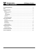
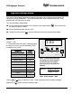
TECHNOLOGIES 834 Sprayer Control Table of Contents Programming Guidelines ________________________________________________________________ 3 Start _____________________________________________________________________________________ 4 System Setup Mode _____________________________________________________________________ 5 Density __________________________________________________________________________________5 Speed Sensor Calibration ___________________________________________________________________
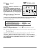
834 Sprayer Control TECHNOLOGIES Programming Guidelines Make sure that all hardware components are properly installed and tested. Before you start the programming process you should first check if the console and all sensors are working properly. Important Preliminary Information Before you begin, we recommend that you review the following Programming Guidelines that control the programming process: ☛ ☛ ☛ ☛ The ☛ The value of a parameter is changed with the changes the parameter rapidly.
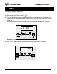
TECHNOLOGIES 834 Sprayer Control Start To begin the programming process: ☛ Read above for programming tips. ☛ Be sure the Master boom switch is “OFF.” ☛ Turn console “ON” by pressing the key. When the control console is turned on, the software version will be displayed for approximately 5 seconds. At the same time all LED’s will be ON. The software version and serial number of the console will be needed when calling for service support.
834 Sprayer Control TECHNOLOGIES System Setup Mode The System Setup Mode contains the programming steps that customize the monitor to the sprayer or sprayer components. These include calibration steps and parameters that, once programmed, will likely never change. To enter the System Setup Mode: ☛ First be sure that the console is ON (if not put it on by pressing the the normal display is visible). ☛ ☛ Ensure the Master boom switch is OFF.
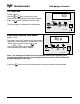
TECHNOLOGIES 834 Sprayer Control SPEED SENSOR CALIBRATION Default = 250 pulses/100 meters The speed sensor needs to be calibrated in order to provide the proper speed reading. The value for this step is the number of pulses generated by the speed sensor in 100 meters. 250 I CAL D 3 sec. = Pro Auto Calibration The speed sensor can be automatically calibrated by driving 100 meters. The console will automatically detect a RADAR sensor (if used).
834 Sprayer Control TECHNOLOGIES Radar r 10.2 A radar speed sensor will be indicated with an "r" on the display e.g. The "r" will automatically appear during the auto calibration process when the console has determined that a radar is being used. When manually entering a radar calibration number the "r" must be turned on by pushing the Auto/Man key. With this key you can toggle between radar or wheel sensor. The calibration value itself is adjusted with the + and I CAL D 3 sec. = Pro keys.
TECHNOLOGIES 834 Sprayer Control TIP SPACING Default = 50 cm 50 Use the + or keys to adjust this value. Once the correct spacing has have been entered, press the key to advance to the next step. I The value shown is represented in centimeters. CAL D 3 sec. = Pro PRESSURE REGULATING MODE Default = byP The default value "byP" indicates that the pressure regulating valve is plumbed in a bypass line. If the default value is correct, press the key.
834 Sprayer Control TECHNOLOGIES Normal Working Mode INTRODUCTION In normal working mode, the display can show four different pieces of information indicated by the LED’s below the display e.g.
TECHNOLOGIES 834 Sprayer Control SPEED DISPLAY In this display the speed in Km/H is shown. Press the 8.5 key to advance to pressure display. I CAL D 3 sec. = Pro PRESSURE DISPLAY In this display the pressure in bar is shown. Press the display. 2.3 key to advance to the tip selection I CAL D 3 sec.
834 Sprayer Control TECHNOLOGIES TIP SELECTION DISPLAY This display is the tip selection display. On the display the two last digits of the VisiFlo color coded tip are shown, e.g. an XR11004 corresponds with _04. (See Table Below) The last selection _P is a programmable selection in case the tips being used do not match one of the preprogrammed flow rates. See the following page for programming instructions on the _P selection. 04 I CAL 3 sec. = Pro keys to select another tip.
TECHNOLOGIES 834 Sprayer Control Programmable Tip As mentioned above the _P section of the Tip Selection Display can be programmed to match the flow rate of the tips on the sprayer if they do not fall into one of the categories listed above. To access the programmable section, while viewing the _P display, simulataneously press the Auto/Man and keys for 3 seconds. _p I CAL D 3 sec. = Pro 1.36 The display will then display a flashing flow rate represented in l/min at 2 bar.
834 Sprayer Control TECHNOLOGIES Operating Instructions SPRAYER CHECKOUT Before spraying check all connections related to the Sprayer Control assembly. Particular attention should be given to the speed sensor to be sure the sensor and bolts or magnets are inline, and properly secured or that the radar is installed at the proper height and correct angle. Very important: Whenever you are working around a sprayer or farm chemicals, be sure to wear protective clothing and eyewear.
TECHNOLOGIES 834 Sprayer Control THE SPRAYING OPERATION You have filled the sprayer tank and have thoroughly mixed the chemical(s). Your application rate has been determined as well as the spray tip you will be using, with the sprayer data programmed into the computer. ☛ Switch the computer on by depressing the I/ key on the display panel. ☛ Toggle the boom switches to their “ON” position, for each of the booms on your sprayer.
834 Sprayer Control TECHNOLOGIES Alarms and Warnings On the 834 Console there are three LED's for indication of alarms or warnings. • The Speed alarm LED flashes when no speed pulses are received during spraying (Master in the ON position). This indicates that there is something wrong with the speed sensor or that you are standing still while spraying.