Spraying Systems Co.
Cable Connections BATTERY FLOW METER (OPTION 1) BATTERY CABLE PRESSURE TRANDUCER (OPTION 2) SENSOR END CABLE SPEED SENSOR SENSOR CABLE LEAD 844 SPRAYER CONTROL PRESSURE REGULATING VALVE VALVE CABLE LEAD BATTERY CABLE LEAD VALVE END CABLE BOOM CONTROL VALVES
Table of Contents Introduction Sprayer Control Installation Mounting Sprayer Components Pressure Regulator in Bypass Mode Pressure Regulator in Throttling Mode Flow meter Boom Control Valves Pressure Transducer Installing the Speed Sensor Assembly Mounting the TeeJet 844 Console Connecting System Components to the Control Console Component Wiring Programming Guidelines Steps to Successful Programming System Setup Mode Programming Steps 1 Setting the Program Mode - U.S./Turf/NH 3/Imperial/S.I.
Introduction Congratulations! And thank you for choosing Spraying Systems’ advanced 844 sprayer control system. With its proper installation and maintenance, you can enjoy many seasons of accurate and uniform spray application with fingertip convenience and ease of operation. Installation and Programming of your control system will be covered in easyto-follow, step-by-step instructions.
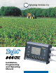
The TeeJet® 844 Sprayer Control basic package for flow based systems could consist of the components shown in this photograph.
Mounting Sprayer Components PRESSURE REGULATOR IN BYPASS MODE All pressure regulating valves for the 844 will be wired for use in a by-pass system. While plumbed in a by-pass mode, with the Auto/Man key in the “MAN” mode, the valve should close when the key is depressed and open when the key is depressed. The pressure regulating valve can also be mounted in a throttling situation as an alternative location. Refer to page 5, and Figures 8 and 8A.
PRESSURE REGULATOR IN THROTTLING MODE In large flow situations, the pressure regulating valve, as shown in Figures 8 and 8A, can be located in the supply line before the boom control valves. If you choose this location, the 844 will need to be properly programmed to reverse the polarity of the valve. This step can be found in the System Setup instructions on page 21. When in throttling mode, the valve should open when the key is depressed, and close when the key is depressed.
FLOW METER To ensure accurate readings, the flow meter (if used) must be mounted 10˝ to 12˝ (25-35 cm) from other pipe fittings, preferably in a vertical position with the flow going up. It should also be mounted with direction of flow arrow pointing toward the boom control valves. Refer to Figures 7A and 8. Be sure the flow meter is plumbed so that all liquid passing through it is routed to the booms and not back to the tank.
Installing the Speed Sensor Assembly Components: Two magnets, Sensor with attached connector cable, and mounting hardware. If you are installing a radar ground speed sensor, follow the instructions supplied with that unit. SPEED STE P 1 Location The speed sensor assembly should be installed on a non-driven wheel to avoid potential errors that are likely to occur from a slipping drive wheel. Refer to Figure 1.
Installing the Wheel Magnets SPEED STE P Check for pre-drilled holes in the wheel rim. If pre-drilled holes are not available, layout a pattern as shown in Figure 4 and drill two 3/8 inch (10 mm) holes, locating them near the outer edge of the rim, if possible and 180° from each other. 2 Place the magnets into each of the two holes on the inside rim and securely fasten using the nuts and washers provided.
SPEED Confirming Speed Sensor Installation STE P Magnetic Wheel Sensor: 4 After your wheel or proximity sensor is installed and once the 844 console is installed and powered up, you can test the speed sensor installation. Connect the wheel speed or proximity sensor to the sensor cable, and in turn connect the sensor cable to the 844 console. When the connection is made, rotate the wheel on which the magnets are installed. If using a proximity sensor, you will be sensing metal objects and not magnets.
MOUNTING THE TEEJET 844 CONSOLE CONSOLE STE P 1 CONSOLE STE P 2 Location Determine the best location for the control console in the cab or operator’s compartment. Allow sufficient clearance, approximately 4-5˝ (10-12 cm) to accommodate for the power and operating cables that will be connected to the cable leads and connectors on the right side of the console.
CONSOLE STE P 3 Power Connection Locate the power cable which has a black connector on one end, and two battery terminal rings on the other. Extend the battery terminal ring end of this cable from the cab to the battery. Note: Some tractors use two 6 Volt batteries as a power source. Make sure there is a total of 12 Volts delivered to the controller by connecting to the (+) terminal on one battery and the (-) terminal on the other battery.
CONSOLE STE P 4 Connecting Component Cables to Console Now that you have the console installed you can begin connecting it to the other components of the 844 system. The standard kit contains a valve end cable that attaches to the boom control valves and the pressure regulating valve on one end, and directly to the lower right cable lead of the 844 on the other end.
CONNECTING SYSTEM COMPONENTS TO THE CONTROL CONSOLE Two cables are provided to connect the sprayer control components to the Control Console: ■ The “Sensor” Cable provides connections to the Flow meter or Pressure Transducer, and Wheel Speed Sensor or Radar Speed Sensor. ■ The “Valve” Cable provides connections for the Pressure Regulating Valve and the Boom Control Valves. Both have a large plug on one end and lead connectors for individual valves or sensors on the other end.
Wiring Layout CONNECT STE P Determine the best cable routing to the sprayer control components on the sprayer. This could be along the flow line, main frame of the sprayer, or wherever the cables can be conveniently secured. Avoid any situation where the cables may lay in puddles, or come in contact with extreme heat sources. 1 Warning: System Components should be mounted at least 3 feet (1 meter) from areas of excessive vibration (i.e. engines) to avoid high frequency interference.
Making the Connections CONNECT STE P Now, extend the cable containing the leads to the Flow meter or Pressure Sensor, and Wheel Sensor or Radar Sensor to the furthest component. Select the appropriate lead and connect to this component. Run the cable to the other component, taking care to safely secure the cable along the route. Refer to figure 11 on page 14. 2 5 Section 3 Section 1 2 3 4 5 1 2 3 Color White Green Yellow Orange Blue BOOM CONTROL VALVE WIRE COLORS VS.
Programming Guidelines IMPORTANT PRELIMINARY INFORMATION Before you begin, we recommend that you review the following Programming Guidelines that control the programming process: ■ For your convenience, the programming of the 844 has been divided into two programming categories; System Setup Mode and Application Setup Mode. ■ Depressing the key once will flash “ ” in the upper left hand corner of the display window.
Steps to Successful Programming To begin the programming process: ■ Read above for programming tips. ■ Be sure the “master” boom toggle switch is “OFF.” ■ Turn console “ON” by depressing the key. When the Control Console is turned on, the software version will be displayed at the top of the display and the serial number will be displayed in the lower half of the display. This information will be needed when calling for service support.
If, however, you have installed a pressure transducer instead, use the or key to key to select “PrS” for a pressure based system. Then, depress the advance to the next step. If both sensors have been installed on the sprayer, this step will determine which sensor will be used by the 844 to determine pressure/flow regulation. If “FLO” is selected, the flow meter will be used to control the flow and the pressure transducer will be used only to display the actual pressure.
Pressure Transducer Low Pressure Calibration (P rEF) P ref 4.0 Default = 4.0 This step is used to calibrate the “0” pressure setting of the pressure transducer installed in your system. The pressure transducer used with the 844 is a current type transducer and uses a 4-20 mA reading. 4.0 mA represents 0 pressure. This step uses an auto-calibration feature to calibrate the transducer. Make sure that the sprayer pump is off and there is absolutely no pressure in the system.
TIPS PER BOOM SECTION Number of Spray Tips Per Boom Section Default = 6 (tips per section in US, trF, iNp and SI Modes) Default = 12 (tips per section 1, 0 for the others in nh3 Mode) While in the Tips Per Boom Section step, the symbol will be flashing at the top of the console display. The console will also display “SEC 1” at the left and a number (6) at the right of the display. The “SEC 1” refers to boom section #1 on your sprayer.
Warning: If the user is using tips other than the TeeJet®‚ VisiFlo®‚ brand, the corresponding colors may not match. In this case, the user should determine the flow rate of the tip being used at 40 psi (2 bar), and enter this flow rate as the programmable tip. NOTE: The flow rate will automatically be displayed at 40 psi (2 bar). This pressure must be used for determining your tip’s flow rate. Actual operation pressure is not important.
REGULATION ADJUSTMENT SPEED Regulation Adjustment Speed Default = 9.5 (bYP Mode) While in this step, the symbol will be flashing at the top of the console display. This step allows you to regulate the speed of the pressure regulating valve to accommodate different application needs. Operating conditions may necessitate a higher or lower response speed for the regulating valve. To change the response time number, simply use the and keys to increase or decrease the number. Any number between 0.0 and 9.
CALIBRATE SPEED Speed Sensor Type Default = 250 Note: During Speed Calibration, the 844 will automatically sense whether a Wheel Speed or Radar Speed Sensor is being used. While in the Speed Calibration Programming Step, the symbol will be flashing at the top of the display. The programmable value (250) will be displayed in the lower right corner of the display. PROXIMITY/MAGNETIC PULSES The speed sensor needs to be calibrated in order to provide the proper speed and area readings.
RADAR SPEED PULSES Automatic Calibration: The automatic calibration of a Radar speed sensor is similar to the automatic calibration of a wheel speed sensor. Refer to the directions above. When the console has determined that a Radar Speed Sensor is being used, rAd will be displayed in the lower left of the console display. Manual Calculation: To manually enter the radar calibration value, first press the Auto/Man key to put the control console into radar mode.
Liquid Specific Gravity (Density) PROGRAM SPECIFIC GRAVITY Default = 1.00 While in the Liquid Specific Gravity (Density) Programming Step, the symbol, will be flashing at the top of the console display. D Weight of Solution Per Gallon Specific Gravity 7.0 lbs. 8.0 lbs. 8.34 lbs.–Water 10.0 lbs. 10.65 lbs.–28%N 10.85 lbs.–30%N 11.0 lbs. 12.0 lbs. 14.0 lbs. .84 .96 1.00 1.20 1.28 1.30 1.32 1.44 1.68 Note: Water weighs 8.34 lb/gal or 1 Kg/L D The default value of “1.
Minimum Regulating Pressure Setting MINIMUM PRESSURE 10 PSI 0.7 bar Default = 10 PSI (0.7 bar) This programming step allows you to set the minimum pressure that the sprayer control will regulate to. Sometimes when the sprayer speed slows down, the control system will regulate the pressure so low that it falls below the manufacturer’s recommended pressure for the spray tip or reduces system flow to the point where the flow meter will stall.
Programming the 844 Sprayer Control System APPLICATION SETUP MODE The Application Setup Mode contains the programming steps that are most frequently changed (target application rate, and nozzles used). Spraying Systems Co. has added this separate setup mode to speed the programming process when minor changes are made in the spraying operation (i.e. changing fields, switching nozzles, changing crops, etc.). The operator can avoid toggling through all of the programming steps unnecessarily.
Select the representative color to match the spray tips being used to apply the desired application rate. Use the or keys to toggle the symbol through the tabbed color strip at the bottom of the display panel. The corresponding flow rate for each color will be displayed in US Gallons Per Minute (Liters Per Minute) {Imperial Gallons Per Minute} at 40 psi (2 bar) at the lower right of the display. If the programmable tip is to be used, toggle the symbol to the “P” tab.
The 844 will immediately calculate what the pressure would need to be to maintain the target application rate at this speed. If the pressure is too high, you will need larger spray tips or will have to slow down. If the pressure is too low, you will need smaller spray tips or will have to speed up. Adjust Pressure: If you wish to adjust the pressure, press the key once so that the pressure “PSI” (Bar) units begin to flash.
Operating Instructions SPRAYER CHECKOUT Before spraying check all connections related to the Sprayer Control assembly. Particular attention should be given to the speed sensor to be sure the sensor and magnets are inline, and properly secured. Very important: Whenever you are working around a sprayer or farm chemicals, be sure to wear protective clothing and eyewear.
THE SPRAYING OPERATION You have filled the sprayer tank and have thoroughly mixed the chemical(s). Your application rate has been determined as well as the spray tip you will be using, with the sprayer data programmed into the computer. ■ Switch the computer on by depressing the key on the display panel. ■ Toggle the boom switches to their “on” position, for each of the booms on your sprayer.
Features BOOST MODE There may be instances where ”on the go” increased or decreased chemical application may be required in certain areas of your field. In situations like this, the and keys will allow you to easily make the necessary adjustments. The boost mode can be activated while spraying in the Auto mode by depressing either the or key once. With each subsequent depression of the key, the application rate will be increased by 10%.
Features FLOW RATE FEATURE The 844 Sprayer Control will measure a flow rate moving through the flow meter in GPM (LPM) {Imp GPM}. This feature is activated by pressing and holding the key while spraying in the normal operating mode. The flow rate display replaces the area/volume display in the lower right portion of the display. Any time the key is pressed while spraying in the normal operating mode the flow rate will be displayed. Releasing the key will cause the display to return to area/volume.
Features PRINTING Optional printers are available for printing a spraying report directly from the 844. This printing feature is only available on 844 consoles that have been upgraded with the communications package. The optional printers and 844 communications package are available through your TeeJet supplier. The printout that you get from the 844 contains memory information that the 844 collects. A sample of this printout is below.
Troubleshooting Guide CONDITION 1 Application Rate Units (GPA, G/1000 ft or l/Ha) continually flash on/off. 2 POSSIBLE CAUSES SOLUTION A Continuous discrepancy of 10% or more between Target Application Rate and Actual Application Rate. Check all components and programming steps related to flow PROGRAMMING B Flow meter pulses C Nozzle Selection In the System Setup mode, move to the flow meter Pulses section on page 18 of the 844 Installation Manual.
CONDITION POSSIBLE CAUSES SOLUTION E Flow meter plumbed incorrectly A flow directional arrow is located on the body of the flow meter. Plumb the flow meter with the arrow in the direction of the flow. The flow meter must be mounted 10˝ to 12˝ (25-35 cm) from other pipe fittings. See 844 Installation Manual page 6. Generally, the flow meter works better when mounted in a vertical position with the flow being directed up. 3 Flow meter turbine symbol continually flashes on/off.
CONDITION POSSIBLE CAUSES SOLUTION 6 Actual total volume applied in GPA, G/1000 ft2, or l/Ha does not match the total area covered. A Speed sensor not calibrated correctly. Recalibrate the magnetic or radar speed pulses in the Calibrate Speed section of the System Setup Mode on page 22-23 of the 844 Installation Manual. B Incorrect nozzle spacing Check the Nozzle Spacing section in the System Setup Mode on page 19 of the 844 Installation Manual to ensure the correct nozzle spacing has been entered.
Flow Meter Calibration The flow meter supplied with your system has been calibrated at the factory and under normal circumstances there may be no need to re-calibrate it. However, the factory calibration setup may not reflect specific sprayer plumbing. Before spraying actual chemicals, the flow meter should be checked for proper calibration. Also, the flow meter is made up of moving parts and can wear over time.
Flow Meter Calibration Example: If the volume displayed is 5% too high, then increase the flow meter calibration number by 5%. If the volume displayed is 5% too low, then decrease the flow meter calibration number by 5%. Method 2 – Known Tip Size Method Step 1 – Check Tip Size Determine what size tip is on the sprayer. An actual flow collection should be done on a representative sample to ensure the tips are not worn. To do this, set the boom pressure at 40psi (2 bar). This must be pressure at the tips (i.
Flow Meter Maintenance DAILY MAINTENANCE LONG TERM MAINTENANCE • Unscrew sensor from the flow meter assembly • Should be performed every 50 hours of operation • Remove flow meter from the system (If Rapid Check, remove the rapid check unit from the body) • Unscrew sensor from the flow meter assembly • Use clean water to wash any impurities out of the flow meter (out of the removable turbine unit if rapid check) • Blow compressed air (Max.
Spraying Systems Co. ® P.O. Box 7900 Wheaton, Illinois 60189-7900 USA Phone (630) 665-5000 • Fax (630) 665-5292 tjtech@spray.