CenterLine Software Version 2.02 Copyrights © 2007 TeeJet Technologies Inc. All rights reserved. No part of this document or the computer programs described in it may be reproduced, copied, photocopied, translated, or reduced in any form or by any means, electronic or machine readable, recording or otherwise, without prior written consent from TeeJet Technologies, Inc.
TABLE OF CONTENTS CHAPTER 1 - INTRODUCTION . . . . . . . . . . . . . . . . . . . . . . . . . . . . . . . 1 STRAIGHT OR CURVED GUIDANCE . . . . . . . . . . . . . . . . . . . . . . . . . . . . . . . . . . . . 1 WIRELESS REMOTE CONTROL UNIT . . . . . . . . . . . . . . . . . . . . . . . . . . . . . . . . . . . 1 LIGHTBAR DISPLAY . . . . . . . . . . . . . . . . . . . . . . . . . . . . . . . . . . . . . . . . . . . . . . . . . 1 MENU ITEMS AND PICK LIST TEXT . . . . . . . . . . . . . . . . . . . . . . . . . . . .
ii
CHAPTER 1 - INTRODUCTION CenterLine is an economical lightbar guidance system that is controlled by a wireless remote. CenterLine provides accurate Straight-Line and Curved Guidance for use in spraying, seeding, and other related jobs at a cost that rivals foam markers. The CenterLine product is equipped with a combination Beacon/WAAS or WAAS only DGPS receiver, providing sub-meter, pass-to-pass positioning accuracy.
The lightbar text window can display a single line of text up to ten characters in length. Figure 1-1 illustrates an example of a single text line that would be displayed on the lightbar. Figure 1-1: Example of Lightbar Text Display Start Arrow buttons Figures with multiple menu items are depicted with menu items above and below, and with submenu items located to the right of the text item currently in view. Figure 1-2 represents several menu items.
Figure 1-3: and Examples Units System Language Next To Start Wireless Remote Control Operation of the CenterLine software occurs via remote keypad input and menu items displayed in the text display area. The Arrow buttons are used to scroll through menus and sub-menus. The Enter button is used to enter menus and sub-menus and accepts the appropriate entry. The Escape (ESC) button acts as a cancel button.
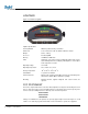
LIGHTBAR Figure 1-5: CenterLine Lightbar Lightbar Specifications Housing Material ABS/Poly carbonate alloy construction. Dimensions 3.70” H x 9.40” W x 3.80” D / 95mm x 240mm x 100mm Weight 0.8 lbs / 0.36 kg Processor Intel StrongARM Memory 16 MB Ram, 2 MB Flash LEDs High-lumen red, yellow, and green radial light pattern and 10-character LED alphanumeric text display. Full brightness control adjustment using wireless remote.
CHAPTER 2 - SETUP It is assumed that the CenterLine system has been properly installed. Refer to the following CenterLine diagrams for system configuration. QUICK START GUIDE First Time Start-Up Sequence 1. Turn ON power to CenterLine. 2. The lightbar will perform a start-up sequence. 3. The lightbar will display the current software version. 4. The lightbar will display . 5. Using the Arrow buttons, scroll until is displayed on the lightbar. Press the Enter button. 6.
Figure 2-1: CenterLine Without DGPS Receiver Lightbar 78-50112 A GPS data cable is required but not provided in the kit.
CENTERLINE SETUP CenterLine Setup allows for the configuration of the CenterLine product to best suit current guidance and mapping needs. For a complete overview of the setup process, refer to Figure 2-31 (page 22). CenterLine Setup consists of three sub-menus: • Guidance • Lightbar • System The top level of CenterLine software contains three menus available for selection: , , and . To access the setup menus, use the Arrow buttons to scroll to and press the Enter button.
Figure 2-4: Guidance Setup Flow Guidance Width Ahead Antenna Status Alarm GPS Type 1 Hz MSG Next To Start Table 2-1: Guidance Default Settings Setting Default Value Change at Initial Startup Width 30.0 feet/10 meters Required Ahead 1.5 seconds Optional Antenna - Direction None Recommended Antenna - Distance 0.0 feet Recommended Antenna - Height 9.8 feet / 2.
Figure 2-5: Swath Manager 5 Setup Guidance Setup Swath Man Table 2-2: Swath Manager Settings Setting Description % Overlap Boom sections are activated and deactivated based on the percentage of boom overlap setting (0%, 50%, and 100%) Sections The number of sections (1-5) active on the system. Width 1-5 The width for each boom 1-5. Delay The delay in seconds to turn the booms on and off when entering/exiting applied zones.
Sections Enter the number of sections that are active in the system. Use the Arrow buttons to scroll to the appropriate number (1 - 5) and press the Enter button to accept the setting. Figure 2-8: Number of Sections Sections 5 Arrow buttons Width Enter button Enter the width in feet / meters for boom section 1 by using the Arrow buttons to scroll through the options, followed by the Enter button. Repeat the process for the remaining boom sections.
Figure 2-11: Guidance Width Width 58.5 Ahead The Look Ahead value, Ahead, is the number of seconds ahead of the vehicle the operator desires the software to calculate the cross track error. Based on the vehicle’s speed and trajectory combined with the look ahead value, CenterLine can determine where the vehicle will be with respect to the current guideline. This setting will vary based on the operator’s driving ability and preference. This value is only used during Parallel Guidance.
Figure 2-14: Establishing Direction to Swath Back Direction Forward Table 2-3: Swath Settings Setting Description Back GPS receiver is behind the swath or delivery point on the vehicle along the center line. Forward GPS receiver is in front of the swath or delivery point on the vehicle along the center line. Antenna - Distance Arrow buttons The Distance setting defines the distance from the GPS antenna to the swath or delivery location (refer to Figure 2-16).
Antenna - Height The Height setting defines the height of the GPS antenna to the ground surface. This value is used only when a tilt sensor is connected. To change the height setting, navigate to , use the Arrow buttons until is displayed, and press the Enter button. Use the Arrow buttons to select and press the Enter button. Using the Arrow buttons, enter the height value until the desired distance is displayed in the text window.
Figure 2-19: Alarm Selection Alarm Off On Table 2-5: Alarm Settings Setting Description Off No applied area detection. On Applied area detection. Alarm will sound. GPS Type Arrow buttons GPS Type indicates to the CenterLine system if the GPS receiver is differentially corrected. To adjust the GPS Type, navigate to , use the Arrow buttons until is displayed and press the Enter button. Options include and .
Figure 2-21: 1 Hz MSG Setting 1 Hz MSG Yes No Table 2-7: 1 Hz MSG Settings Setting Description Yes When the data rate of the GPS receiver is set to 1 Hz, a message is sent to the lightbar and the guidance function is disabled. No When the data rate of the GPS receiver is set to 1Hz, a message is sent to the lightbar when the operator first begins operation, but guidance is allowed. Lightbar Lightbar setup allows the selection of several parameters related to the lightbar.
Table 2-8: Lightbar Menu Settings Setting Default Value Change at Startup Spacing 1.5 feet Optional Mode Swath Optional Text 1 X-Track Error Optional Text 2 Applied Area Optional Steer Bar No Optional Spacing Arrow buttons The Spacing setting allows the selection of the distance that a single light on the lightbar LED represents. To change the spacing setting, navigate to , use the Arrow buttons until is displayed and press the Enter button.
Table 2-9: Mode Settings Setting Description Swath The center stack of LEDs represent the current guideline. Steer the vehicle to bring the moving LED back to center. Vehicle The center stack of LEDs represent the vehicle’s position. Steer the vehicle to bring the center lights toward the moving LED. Text 1 and Text 2 Text 1 and Text 2 settings allow the operator to select text messages from pre-determined guidance information messages.
Table 2-10: Text 1 Settings Arrow buttons Message Description X-Track Displays the error (in distance) between the current guideline and the vehicle position. Swath # Displays the current guideline number. Ground Speed Displays the vehicle ground speed. Area Applied Displays the amount of area covered, sprayed, or spread in acres or hectares. COG Course on Ground, displays the vehicle heading in degrees. Off When OFF is selected, no message is displayed in the message slot.
Steer Bar The Steer Bar setting determines how the LED steering display will appear. The LEDs represent the vehicle track in relation to the current guideline. They can be displayed as a single LED or as a solid bar. To change the steer bar setting, navigate to , use the Arrow buttons until is displayed and press the Enter button. Use the Arrow buttons to select either YES or NO. Press the Enter button to save the setting and return to the menu.
Table 2-13: System Settings Setting Default Value Change Upon Startup Unit US Optional Language English Optional Unit System units allow the selection of either U.S. or Metric units of measurement. To change the system units, navigate to and press the Enter button. Use the Arrow buttons to navigate to and press the Enter button. Options are either US or Metric. Select the appropriate option and press the Enter button to save the setting and progress to the menu.
Figure 2-30: Language Options Language English Swedish Danish Dutch German French Italian Portuguese Spanish Polish Russian CenterLine 2.
Figure 2-31: CenterLine Setup Flow Diagram Start Setup Guidance Tools Swath Man %Overlap 0% Width 30.0 (default) Sections 50% Ahead 1.5 (default) Width 1-5 100% Antenna Direction Forward Delay Back Next Distance 0.0 (default) To Start Height 9.8 (default) Next Status Off On Alarm Removed from menu setup when Swath Manager 5 is connected Off On GPS Type DGPS GPS 1 Hz MSG Yes No Next To Start Lightbar Spacing 1.
TOOLS The Tools menu contains several functions that provide basic systems diagnostics. The tools menu is accessed from the main menu. Use the Arrow buttons to select and press the Enter button.
Receiver Arrow buttons The Receiver diagnostic test displays the attached GPS receiver’s current configuration and status. The information is displayed in the text window of the lightbar. To begin the receiver check, navigate to and press the Enter button. Use the Arrow buttons to select and press the Enter button. The lightbar will display the diagnostic message.
To re-calibrate the e-Dif receiver, navigate to and press the Enter button. Use the Arrow keys to select and press the Enter button. The lightbar will display until the receiver is re-calibrated, followed by once the process is complete. e-Dif Info Arrow buttons The e-Dif Info function appears only when the CenterLine system detects that an e-Dif GPS receiver is present and calibrated.
26 Chapter 2 - Setup
CHAPTER 3 - OPERATION Operation is started by pressing the Enter button when is displayed on the lightbar. The menu item is at the highest menu level. Start can be easily reached from most menu levels by using the Arrow buttons to find and pressing the Enter button.
Note: Apply On/Off does not turn the application on and off. It simply notifies the CenterLine system of the application status. and do not appear if is set to ON. Arrow buttons Apply On/Off If no SM5 is being used and the setting is set to OFF, the Apply On/Off information must be provided to the CenterLine system manually.
Figure 3-3: A+ Feature Area Determination The area of the current job or field is important. CenterLine allows the determination of the area of a field by driving the perimeter. This can be accomplished while driving the first headland circuit during Headland Guidance. To determine the area of the field, use the Arrow buttons on the operation menu to locate . Press the Enter button. The lightbar will display or .
Return To Point CenterLine allows the operator to mark a point of reference in the field in which to return at a later time. Typically the Return to Point feature is used to mark a location when stopping guidance and starting in the same location and direction at a later date and time. This Return to Point location is stored in the field’s trajectory data and is lost if is select. It is retained if is selected.
Reference Guideline While operating in Headland Guidance, the operator has the option to mark Points A and B on the reference guideline used for Straight-Line or Curved AB Guidance modes. It is easier to mark Points A and B for the Straight-Line or Curved AB Guidance modes while driving along a straight edge of a field. Refer to CHAPTER 3 - CURVED AB GUIDANCE for additional information.
Figure 3-7: Example of Completed Field Headland Guidance Lightbar Graphics CenterLine’s Headland Guidance uses a lightbar text display graphic that aids the operator when navigating parallel to a curved swath. The X-Track LED functionality that is used during Straight-Line and Curved AB mode is also used during Headland Guidance. A projected swath path graphic is displayed in the text display area of the lightbar. The projected path is comprised of four horizontal bars.
Figure 3-9: Lightbar - Right Turn Approaching Figure 3-10: Lightbar - Hollow Path During First Headland Pass STRAIGHT-LINE GUIDANCE Straight-Line Guidance provides vehicle guidance along straight lines based on a reference guideline. The initial step is to establish the reference guideline. The reference guideline is used to calculate all other parallel guidelines. Refer to CHAPTER 3 - MARKING POINTS A AND B for additional information. To mark the initial Point A, drive along the first swath path.
Figure 3-11: Example of Straight-Line Guidance When navigating a turn at the end of the field, the lightbar will display the distance to the next swath. Figure 3-12: Example of CenterLine Turn Curved AB Guidance Curved AB Guidance works similarly to Straight-Line Guidance except it provides vehicle guidance along curved lines based on a curved reference line. The first step is to establish a reference guideline. The reference guideline is used to calculate all other guidelines parallel to the path.
Figure 3-13: Curved A-B Guidance The lightbar will immediately display . To establish Point B, press the Enter button once the vehicle travels over the desired Point B location. The reference line is now established. The lightbar will begin displaying X-Track guidance information as well as user-selected messages that were defined during Lightbar Setup (refer to CHAPTER 2 - LIGHTBAR for additional information).
Figure 3-14: Applied Area Detection Neighboring Swath Detection Applied area detection also notifies the operator when the vehicle crossed into a previously applied neighboring swath. Figure 3-15 illustrates an example on an applied area overlap. The vehicle can overlap up to 25% of the swath width without notification. Once the edge of the vehicle overlaps the neighboring swath by 25% or more, the lightbar will display .
Table 3-1: Lightbar Index Lightbar Description Mark A. Displayed when establishing Point A of the reference guideline. Mark B. Displayed when establishing Point B of the reference guideline. Swath #. A user-selected lightbar message. When not on the initial guideline, the first character is either L (left) or R (right) of the initial guideline. The number identifies how many lines left or right of the initial guideline. X-Track. A user-defined lightbar message.
Lightbar Description Area Applied. A user-defined lightbar message indicating the current amount of area applied in acres. The system units are set to US. Area Applied. A user-defined lightbar message indicating the current amount of area applied in hectares. The system units are set to Metric. Applied Area Detection. This message is displayed when the vehicle is within a previously applied area. The red stoplight (located on the far right) is illuminated. Curved guidance information graphics.
Lightbar Description System Warning. This message is displayed when there is a complete loss of GPS signal to the GPS receiver or Smartpad. Guidance calculations are stopped until DGPS signal resumes. Lightbar Version Message. This message is displayed when the user starts CenterLine or runs the lightbar test. This number will vary based on the lightbar version and model. SWATH MANAGER 5 Swath Manager 5 should be configured as illustrated in the following diagrams.
Figure 3-16: Installation of Swath Manager 5 Lightbar 78-50111 Power Cable 45-05324 GPS In Not used Power Cable 45-05324 Lightbar 78-50111 IGN Sense IGN Sense GPS In Status Detect (not used) Cable SM5 to CenterLine 45-05461 Swath Manager 5 78-08065 Not used SM5 Controller Harness TeeJet - 45-05462 Raven - 45-05463 Status Detect (not used) Cable SM5 to CenterLine 45-05461 SM5 Controller Harness TeeJet - 45-05462 Raven - 45-05463 Swath Manager 5 78-08065 To accessory power or battery Existing swit
Figure 3-18: Switch Setting Example for Swath Manager 5 Rate Controller Swath Manager 5 Master and Boom Sections ON Auto Boom Engaged Master ON Boom Sections OFF TILT COMPENSATION MODULE CenterLine must be loaded with Software Version 1.10 or higher to be compatible with the Tilt Compensation Module. The Tilt Module must be leveled (refer to CHAPTER 2 - LEVEL for additional information) and the antenna height must be set (refer to CHAPTER 2 - ANTENNA for additional information).
Figure 3-20: Tilt Compensation Module Tilt Compensation Module Installation • Mount the Tilt Compensation module as close to the center of the vehicle side as possible. • Mount the module on a plain parallel to the GPS antenna so that both the antenna and the sensor tilt the same degree. • Mount the module so the sensor is level and the connector is pointing upward. • The module should be mounted rigidly to minimize vibration. Vibration will degrade the ability to sense tilt.
Figure 3-21: Tilt Compensation Module System RX370P 78-50148 Tilt Sensor 78-08038 CenterLine GPS Data Cable 45-05337 GPS In Back Lightbar 78-50111 CenterLine Tilt Sensor Cable 45-05442 GPS Out CenterLine Power Cable 45-05324 Status Detect IGN Sense EXITING OPERATION To exit operation/guidance, press the Esc button or use the Arrow buttons to scroll through the operation menu until is displayed on the lightbar and press the Enter button.