SWATH XL / GUIDELINE SMARTPAD II USER GUIDE Software Version 4.02 98-05067 R0 Midwest Technologies 2864 Old Rochester Road Springfield, IL 62703 217.753.8424 www.mid-tech.com www.teejet.
SmartPad II Software Version 4.02 Copyrights © 1999 Midwest Technologies Inc. All rights reserved. No part of this document or the computer programs described in it may be reproduced, copied, photocopied, translated or reduced in any form or by any means, electronic or machine readable, recording or otherwise, without prior written consent from Midwest Technologies, Inc.
Table of Contents Chapter 1 - Introduction .............................................................................1 Welcome to SmartPad II ..................................................................................................2 What’s New in Version 4.02 .........................................................................................4 SpartPad II Handheld Button Functions ........................................................................
SmartPad II Software Version 4.02 First Time Setup Process ..................................................................................................7 SmartPad II Main Launcher ...........................................................................................8 Launching an Application ................................................................................................9 Main Setup ...................................................................................................
Data Examples ..................................................................................................................18 Example 1: All Data Menu Items Set to OFF .......................................................18 Example 2: Store As Applied Data Only ..............................................................19 Example 3: Creating or Showing an Existing Field Boundary............................. 20 Example 4: Setting up the Point and Hazard Mapping Objects ...........................
SmartPad II Software Version 4.02 Applied Area Detection .................................................................................................. 62 Creating a Field Boundary............................................................................................. 64 Mapping Points and Hazards .........................................................................................67 Hazard Detection ..............................................................................................
Lightbar Index ................................................................................................................ 40 Chapter 4 Notes ...............................................................................................................42 Chapter 5 - Field Mapping ..........................................................................1 About the Mapper Application ........................................................................................
SmartPad II Software Version 4.
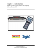
Chapter 1 - Introduction Simple, straight forward guidance and mapping. Software Version 4.02 Midwest Technologies Inc.
SmartPad II Software Version 4.02 Welcome to SmartPad II SmartPad II is a GPS driven swath guidance and mapping system. The SmartPad II system comes complete with Lightbar, Interface cable and SmartPad II. Guidance The SmartPad II Guidance software allows an operator to perform product application while receiving guidance information from the Lightbar. The operator can select between four different guidance modes, Parallel, Curved, Curved A-B, and Center Pivot.
SmartPad II Software Version 4.02 Data collected using SmartPad II software can be viewed, edited or converted into other files formats using the Fieldware - MapManager software, or imported directly into several standard Agricultural GIS packages on the market today. This User’s Guide describes how to install, configure and use the SmartPad II product.
SmartPad II Software Version 4.02 What’s New in Version 4.02 There is one new application and several new features released in Version 4.02.
SmartPad II Software Version 4.02 SpartPad II Handheld Button Functions One of the new features on the SmartPad II is the ability to change the backlight and lightbar brightness On The Go! Please review Figure 1-1 to see which buttons control the screen and backlight.
SmartPad II Software Version 4.02 SmartPad II Installation Instructions Unpacking Your System Open the shipping box and examine the contents for any signs of damage. Please notify the shipper and MID-TECH Customer Support of any damage to the shipping box or its contents. Make sure you have received all items that you purchased with the SmartPad II System. Contents may vary according to what you ordered. Table 1-1 lists the standard components that should arrive with your SmartPad II system.
SmartPad II Software Version 4.02 GPS Antenna Care should be taken as to where you locate the D-GPS antenna. The most accurate D-GPS system in the world is of no value if the antenna is located incorrectly. For any MID-TECH application employing guidance, the GPS antenna should be located along the long axis center line of the vehicle. If the vehicle long axis center line and the center of the spray boom are not the same, i.e.
SmartPad II Software Version 4.02 SmartPad II and Interface Cable The SmartPad II and Interface cable should be located in the cab so that the operator can easily reach, view and operate the system. See Figure 1-4 for instruction on how to connect the Lightbar and SmartPad II to the interface cable. Make sure the interface cables are not under any excess strain, can not be closed in a cab door or window, or stepped on by the operator.
SmartPad II Software Version 4.02 System Specifications and Requirements Lightbar • ABS / Polycarbonate alloy construction, • Dimensions: 16" W x 3" H x 3" D (405 mm x 76 mm x 76 mm), • Weight: 8 oz. (.22 Kg.), • Molded cables with weatherproof connectors, • High-lumen red, yellow and green LEDs, • 8 character, high-intensity alpha-numeric LED display.
SmartPad II Software Version 4.02 CompactFlash Card Instructions Inserting the CompactFlash Card The following instructions describe the basic procedure for inserting the optional 128MB CompactFlash Data card into the SmartPad II: • With power off, locate the CompactFlash card socket on the top of the SmartPad II, see Figure 1-5. • Insert the CompactFlash card into the CompactFlash card socket. Make sure that the CompactFlash card logo is facing out.
SmartPad II Software Version 4.02 Storing Data on the CompactFlash Card If you purchase the optional CompactFlash card with the SmartPad II product, you will be able to store As Applied, boundary and point data to the card. The CompactFlash card must be inserted into the SmartPad II card slot during the real-time guidance process. No data is stored internal to the SmartPad II.
SmartPad II Software Version 4.02 Fieldware/SmartPad II File Types The SmartPad II software can store and view three different types of files, GMF, RCD and BND, all described below in more detail. These file types are also compatible with the MID-TECH Fieldware software suite. That means data collected using the SmartPad II product can also be used in the Fieldware software suite. You can also use any RCD, BND or GMF file that was created using the Fieldware software suite with the SmartPad II product.
SmartPad II Software Version 4.02 BND The primary purpose of the BND file is to contain the boundary data for a particular field. Perimeter data stored in a BND file can be viewed as a background map in several of the other Fieldware software applications. Boundary files can be created and appended to in SmartPad II, Fieldware-Mapper, Fieldware-Guide and Fieldware-ARM applications.
SmartPad II Software Version 4.
Chapter 2 - Software Overview An introduction on how to use SmartPad II software. Software Version 4.02 Midwest Technologies Inc.
Fieldware for Smartpad II Software Version 4.02 SmartPad II Software Overview The SmartPad II software suite is made up of a Main Launcher and three software applications (programs), Guidance, Nav2Point and Mapper. Each application can be broken down into two main components, Setup and Real-Time Mapping. Each of these components are described in more detail in following chapters. Figure 2-10 shows a flow diagram of the SmartPad II software suite.
Fieldware for Smartpad II Software Version 4.02 Operating SmartPad II Software The SmartPad II software was designed to be both easy and intuitive to use. Once an initial setup process is completed, starting up and running a SmartPad II software application can require as few as three key-strokes. The rest of this section will describe the SmartPad II software and how to operate it. Reading the rest of this section is highly recommended.
Fieldware for Smartpad II Software Version 4.02 Screen Selection Touch Screen To make a selection use a stylus and single tap the screen on the desired menu. Manual Selection Items can only be selected when highlighted. Use the Up and Down arrows Press Enter to highlight the desired selection. to select. Data Entry On-Screen Keyboard Select the desired menu to be changed. Select the Keyboard icon to bring up the on screen keyboard.
Fieldware for Smartpad II Software Version 4.02 . Current menu page name. (Setup Menu) Menu Items Highlighted menu item using the up and down arrow keys Key code box showing which keys are available for use. Info Bar displaying brief description of the highlighted menu item. Figure 2-2: Menu Page Example Dialog Boxes The SmartPad II software uses dialog boxes for entering or selecting settings and values associated with each menu item.
Fieldware for Smartpad II Software Version 4.02 Current setting displayed. Description of the displayed setting. Figure 2-3: Pick Dialog Box Example Dialog cell with current value displayed.
Fieldware for Smartpad II Software Version 4.02 First Time Setup Process The first time you start up the SmartPad II, you should also make sure that the current date and time are set correctly, see “Set Date and Time” on page 2-29 for more details. Power Unit On Connect the SmartPad II to the SmartPad II Interface Cable, see Figure 2-5, and apply 12 VDC power. It is not necessary to have the Lightbar or GPS receiver connected and running to change any of the settings.
Fieldware for Smartpad II Software Version 4.02 SmartPad II Main Launcher The Main Launcher is the first menu page you will see after powering up the SmartPad II, Figure 2-6. This is the top Menu page and from here you can launch an application (Guidance, Nav2Pt, or Mapper), access system level setup parameters and run diagnostic tools and utilities. See Figure 2-7 for an overview of the entire SmartPad II software suite. Each sub-menu is discussed in greater detail below.
Fieldware for Smartpad II Software Version 4.02 Launching an Application From the Main Launcher, the user can start (launch) a SmartPad II software application. In version 4.02 there are three software applications Guidance, Nav2Pt, and Mapper. To launch an application highlight the desired application name, using the up and down arrow keys on the smartpad keypad, and then press enter. The main application menu will appear.
Fieldware for Smartpad II Software Version 4.02 Main Setup The Main Launcher Setup Menu, Figure 2-19, contains all setup parameters that are common to both Guidance, Nav2Pt, and Mapper. Currently there are four setup menu items found in the Main Setup; System, SmartPad, GPS Receiver and Communications, Figure 2-10 shows the flow diagram for the Main Setup.
Fieldware for Smartpad II Software Version 4.02 Communications Setup The Communications Setup menu defines the SmartPad II GPS serial port parameters. There are four menu items associated with this menu page, Baud rate, Data Bits, Stop Bits and Parity, see Table 2-1. To access the Communications menu page, highlight the Setup menu item in the Main menu page and press . This takes you to the Setup menu page, see Figure 2-11 (right side).
Fieldware for Smartpad II Software Version 4.02 Port Baud Rate The Baud Rate menu item sets the GPS port baud rate on the SmartPad II, see Table 2-2. To change the Baud Rate setting; highlight the Baud Rate menu item and press will appear. Select the desired setting using the arrow keys . The Port Baud Rate dialog box , once the desired setting is selected, press return back to the Communications setup menu, see Figure 2-12.
Fieldware for Smartpad II Software Version 4.02 Port Data Bits The Data Bits menu item sets the GPS port Data Bits on the SmartPad II, see Table 2-3. To change the Data Bits setting; highlight the Data Bits menu item and press appear. Select the desired setting using the arrow keys . The Port Data Bits dialog box will , once the desired setting is selected, press to return back to the Communications setup menu, see Figure 2-13.
Fieldware for Smartpad II Software Version 4.02 Port Stop Bits The Stop Bits menu item sets the GPS port Stop Bits on the SmartPad II. There are no options for this menu item and therefore cannot be changed, see Figure 2-14.
Fieldware for Smartpad II Software Version 4.02 Port Parity The Parity menu item sets the GPS port Parity on the SmartPad II, see Table 2-4. To change the Parity setting; highlight the Parity menu item and press Select the desired setting using the arrow keys . The Port Parity dialog box will appear. , once the desired setting is selected, press to return back to the Communications setup menu, see Figure 2-15.
Fieldware for Smartpad II Software Version 4.02 SmartPad II Setup SmartPad II setup defines all parameters associated with the SmartPad II. There are two SmartPad II setup menu items, Display Brightness and Display Backlight. SmartPad II Setup default values are listed in Table 2-5. These menu items can adjusted using the buttons on the SmartPad II handheld. See Bulletin 98-01122 for button description. The SmartPad II will default to menu settings when the unit is powered off.
Fieldware for Smartpad II Software Version 4.02 Display Brightness The Display Brightness setting allows you to set the SmartPad II display brightness. The available settings are 1 through 10, where 10 is the brightest setting. To change the Display Brightness setting; highlight the Brightness menu item and press dialog box will appear. Select the desired Brightness setting using the arrow keys level is selected, press .
Fieldware for Smartpad II Software Version 4.02 Display Backlight The Display Backlight setting controls the SmartPad II display backlight. This menu item can be set to On or Off. To change the Display Backlight setting; highlight the Backlight menu item and press dialog box will appear. Select the desired setting using the arrow keys press . The Display Backlight , once the desired setting is selected, to return back to the SmartPad II setup menu, see Figure 2-18.
Fieldware for Smartpad II Software Version 4.02 System Setup System setup defines certain system parameters that will affect the entire SmartPad II software suite. There are two System setup menu items, Unit and Language, see Table 2-7. To access the System menu page, highlight the Setup menu item in the Main menu page and press . This takes you to the Setup menu page, see Figure 2-19 (right side). Within the Setup Menu select the System menu item using the arrow keys . Press to enter the System menu page.
Fieldware for Smartpad II Software Version 4.02 Unit The Unit menu item defines the SmartPad II measurement system. There are two choices, US and Metric. The unit set in this menu field will effect the entire SmartPad II software suite. To change the System Unit; highlight the Unit menu item and press Select the desired unit setting using the arrow keys . The System Unit dialog box will appear. , once the desired unit is selected, press to return back to the System setup menu, see Figure 2-20.
Fieldware for Smartpad II Software Version 4.02 Language The Language menu item defines the user language that will be used through out the entire SmartPad II software suite. All languages that are available to the SmartPad II software suite are stored in the Support folder on the PCMCIA Card. To change the System Language; highlight the Language menu item and press . The System Language dialog box will appear.
Fieldware for Smartpad II Software Version 4.02 GPS Receiver GPS Receiver setup defines DGPS Type Accuracy. GPS Receiver Setup default values are listed in Table 2-9. To access the GPS Receiver menu page, highlight the Setup menu item in the Main menu page and press . This takes you to the Setup menu page, see Figure 2-22 (Left side). With in the Setup Menu select the GPS Receiver menu item using the arrow keys . Press to enter the GPS Receiver menu page.
Fieldware for Smartpad II Software Version 4.02 DGPS Type The DGPS Type defines the type and accuracy of the DGPS source used with your GPS Receiver. This setting defines which set of vehicle dynamic parameters should be used in guidance and point navigation. To change the Display Backlight setting; highlight the Backlight menu item and press dialog box will appear. Select the desired setting using the arrow keys press .
Fieldware for Smartpad II Software Version 4.02 SmartPad II Tools SmartPad II comes with a set of hardware diagnostic tools that will come in handy when trouble shooting a GPS receiver or lightbar. You can also set the system clock. To access the Tools menu page, highlight the Tools menu item in the Main Launcher menu page and press . This takes you to the Tools menu page, see Figure 2-24.
Fieldware for Smartpad II Software Version 4.02 Receiver Status The Receiver Status tool allows you to quickly determine if your GPS receiver is operating properly. A Status window displays easy to understand text information about the operating status of your GPS receiver. The Serial Data Sample windows displays the current raw position string coming from the GPS receiver. The Last Position window displays the current position (Latitude, Longitude) in decimal degrees.
Fieldware for Smartpad II Software Version 4.02 GPS Logger The GPS Logger tool is used to log and store the GPS coordinates during a session. This tool would be used to create a.raw file that could be ran using Mid-Tech’s GPSsim program to simulate a live GPS input. The most common use of this feature is to simulate GPS to a SmartPad II system without moving. To use this tool select the Data Logger menu and create a Log File name see Figure 2-26. Once a name is created select go and begin to drive.
Fieldware for Smartpad II Software Version 4.02 Lightbar Test The Lightbar Test diagnostic allows the users to determine if the SmartPad II is communicating to the lightbar. The Lightbar Test diagnostic can also be used to determine if any of the guidance LEDs or LEDs in the text display are not working properly. To run the lightbar test program, highlight the Lightbar Test menu item using the keys. Once highlighted press . This will automatically start the lightbar test program.
Fieldware for Smartpad II Software Version 4.02 Delete Files The Delete Files tool allows the operator to view and delete individual or all files stored on the CompactFlash data card. The data card must be inserted in the SmartPad II prior to boot up (powering on). To delete files select the Delete Files menu and then select the desired file to be delete and press enter.
Fieldware for Smartpad II Software Version 4.02 Set Date and Time You may need to set the date and time on the SmartPad II. Several features related to the SmartPad II software will depend on the current date and time. All data file creation will be tagged with a date and time stamp. The auto-file name feature will also use the current date to create the file name, therefore it is important that the SmartPad II date and time are correct.
Fieldware for Smartpad II Software Version 4.02 Clock The Clock program turns your lightbar into a clock by displaying the time in the text display window on the lightbar. The time displayed will be based on the system time. To display time on your lightbar, highlight the Clock menu item using the keys. Once highlighted press This will automatically display the time on your lightbar.
Fieldware for Smartpad II Software Version 4.
Fieldware for Smartpad II Software Version 4.
Chapter 3 - Real-Time Guidance Mapping product application in real-time using guidance. Software Version 4.02 Midwest Technologies Inc.
SmartPad II Software Version 4.02 About the Guidance Application Using the lightbar, the guidance function provides the operator with clear and intuitive steering assistance as well as real-time application information. The operator can select between four different guidance modes, Parallel, Curved, Curved A-B, and Center Pivot. Using SmartPad II you can map field boundaries while applying products around the headlands, perform guidance in most any weather and visibility conditions.
SmartPad II Software Version 4.02 Guidance Setup Guidance setup allows the user to set up several parameters that pertain to guidance functionality. There are five guidance related menu items, Swath Width, Look Ahead, Direction to Swath, Distance to Swath and Status Detect, see Figure 3-2 and Table 3-1. To access the Guidance menu page, highlight the Setup menu item in the Main menu page and press . This takes you to the Setup menu page, see Figure 3-1.
SmartPad II Software Version 4.02 Setting Name Default Value Change at 1st Time Start Up Swath Width 0.0 Required Look Ahead 2.0 s Optional Direction to Swath None Recommended Distance to Swath 0.0 ft.
SmartPad II Software Version 4.02 Swath Width The guidance parameter Swath Width is the distance between guidelines. This width is typically determined by the vehicle swath width or spread area, see Figure 3-3. Setting the swath width slightly smaller than the actual width will reduce skips. Setting the swath width slightly larger than the actual swath width will reduce overlap. Figure 3-3: Example of Swath Width To change the Swath Width value; highlight the Swath Width menu item and press will appear.
SmartPad II Software Version 4.02 Look Ahead The Look Ahead value is the number of seconds ahead of the vehicle you would like the SmartPad II software to calculate the cross track error. Based on the vehicles speed and trajectory and this look ahead value, SmartPad II can determine where the vehicle will be with respect to the current guideline. This setting will vary based on the vehicle operators driving ability and preference. This value is only used with the guidance pattern Parallel.
SmartPad II Software Version 4.02 Direction to Swath The guidance parameters, Direction to Swath and Distance to Swath, are used to define the spatial relationship between the GPS antenna and the product delivery location. Examples of a product delivery location would be the boom on a sprayer or the spinner box on a fertilizer spreader. The position of the swath with respect to the GPS antenna will be used to accurately create an As Applied map.
SmartPad II Software Version 4.02 Distance to Swath The guidance parameters, Distance to Swath and Direction to Swath, are used to define the spatial relationship between the GPS antenna and the product delivery location. Examples of a product delivery location would be the boom on a sprayer or the spinner box on a fertilizer spreader. The position of the swath with respect to the GPS antenna will be used to accurately create an As Applied map.
SmartPad II Software Version 4.02 Status Detect The Status Detect menu item is used to auto detect vehicle boom status. When Status Detect is properly implemented, SmartPad II will detect when product delivery is on or off based on the vehicles master boom switch. This will eliminate the need to press the spray on and spray off software button in the SmartPad II software during guidance. This is accomplished by connecting the status detect wires to vehicle boom control switch.
SmartPad II Software Version 4.
SmartPad II Software Version 4.02 GPS Type GPS Type allows you to select between DGPS mode and GPS mode. Changing this setting on your SmartPad II does not make any changes to your GPS receiver. If you want to operate without Differential corrections you may have to turn off corrections in your GPS receiver. To change the GPS Type setting; highlight the GPS Type menu item and press appear. Select GPS or DGPS. Then press . The GPS Type dialog box will to return back to the Guidance setup menu.
SmartPad II Software Version 4.02 GPS Data Rate Data rate allows you to select between 5 Hz and 1 Hz position data rate. This is for user’s who have a GPS receiver that only sends data at 1 Hz. Operating guidance at 1 Hz is not recommended, you will see degraded guidance performance when running in this mode. To change the Data Rate setting; highlight the GPS Data Rate menu item and press will appear. Select 1Hz or 5Hz. Then press . The Data Rate dialog box to return back to the Guidance setup menu.
SmartPad II Software Version 4.02 Data Setup The Data Setup menu page contains menu items that allow you to set up how you would like to create and store data during the real - time portion of SmartPad II. There are three menu items under data; As Applied, Boundary and Map Objects, see Figure 3-15 and Table 3-5. All of these menu fields will directly affect how fast the you can start guidance.
SmartPad II Software Version 4.
SmartPad II Software Version 4.02 As Applied The As Applied menu item defines if As Applied data will be stored to the CompactFlash card during the real time guidance process. If this is set to No, then no As Applied data will be stored. If set to Yes then As Applied data will be stored to the CompactFlash card. As Applied data is not stored internally in the SmartPad II.
SmartPad II Software Version 4.02 Boundary The Boundary menu item allows you to indicate if you want to Show or create a field boundary. An existing boundary can be displayed in the background of the guidance view page. Field boundaries can also be created while applying product to the headland area of a field, see Table 3-7. To change the Boundary setting; highlight the Boundary menu item and press will appear. Select the desired setting using the arrow keys .
SmartPad II Software Version 4.02 Map Object The Map Object menu item provides the ability to map points in the field during the real-time guidance process. There is a selection of several point types, or select Off, see Table 3-8. For object selections, named point and named hazard, you will be prompted for the object name once the Start Guidance menu item is pressed. To change the Map Object setting; highlight the Map Object menu item and press will appear.
SmartPad II Software Version 4.02 Data Examples The following is a series of data storing examples using the menu items described in the Data menu section. Example 1: All Data Menu Items Set to OFF This example describes how to start guidance with no As Applied data, or boundary file information and no mapping objects on the go, Figure 3-19. Therefore when the Start Guidance menu item is selected the software will go directly in to the real-time guidance process.
SmartPad II Software Version 4.02 Example 2: Store As Applied Data Only This example describes how to store As Applied data, there is no boundary mapping or mapping objects. Figure 3-21 shows how the Data menu is setup for Example 2. From the Data menu press to return to the Main Menu.
SmartPad II Software Version 4.02 To name an As Applied, highlight the As Applied menu item using , Figure 3-23 (left side). Pressing will bring up the As Applied dialog box, Figure 3-23 (right side). There are three options once in the As Applied File dialog box, Auto Name, New File or selecting an existing file. The Auto Name option will automatically name the As Applied file using the current date using the format mmddyyyy-#.
SmartPad II Software Version 4.
SmartPad II Software Version 4.02 Example 4: Setting up the Point and Hazard Mapping Objects This example describes how to setup SmartPad II to map point objects while running guidance. Refer to “Map Object” on page 3-17 for a detailed description of what type of objects can be selected and how to select an object in the Data menu. In this example a Named Point was selected in the Data menu, as shown in Figure 3-27.
SmartPad II Software Version 4.02 The Map File menu item defines the file where the mapping object Named Point will be stored, this file can be created, or an existing file name can be selected, see Figure 3-29. Figure 3-29: Selecting a Map File Name The Object Name menu item is where you will enter the name of the Named Point mapping object Figure 3-30. See Table 3-8, “The Map Object Menu Item Settings,” on page 3-17 for more description on the Named Point mapping object.
SmartPad II Software Version 4.02 Lightbar Setup The Lightbar Setup menu is accessed from the Main Menu Launcher Setup item. There are nine lightbar menu items associated with the Lightbar Setup process; Drive Sensitivity, Display Mode, Parallel Message 1, Parallel Message 2, Parallel Message 3, Curved Message, LED Brightness, Alarm and Hazard Range, see Figure 3-32.
SmartPad II Software Version 4.02 Figure 3-32: Lightbar Setup Flow Diagram Setting Name Default Value Change at 1st Time Start up Lightbar ON Optional Drive Sensitivity 1.5 ft. Optional Display Mode Swath Optional Parallel Message 1 X-Track Error Optional Parallel Message 2 Applied Area Optional Parallel Message 3 Off Optional Curved Message Off Optional LED Brightness 7 Optional Alarm All Optional Hazard Range 200 ft.
SmartPad II Software Version 4.02 Use Lightbar Allows the user to turn the lightbar on or off. To change the Use Lightbar setting; highlight the Use Lightbar menu item and press box will appear. Select the desired setting using the arrow keys . The Use Lightbar dialog , once the setting is selected, press return back to the Lightbar setup menu, see Figure 3-33. Figure 4-33: Setup Lightbar Use Lightbar? Setting Description No The lightbar will not be used while Guidance is running.
SmartPad II Software Version 4.02 Drive Sensitivity The Lightbar Menu item, Drive Sensitivity, allows you to set the distance you would like a single light on the SmartPad II Lightbar to represent. If a value of 1.5 feet is entered, then each light on the lightbar will be equal to 1.5 feet. This allows you to quickly determine how far off the guideline you are.
SmartPad II Software Version 4.02 Display Mode The Lightbar Display Mode setting defines how the user will interpret the row of LEDs located on the lightbar. The center stack of Green LEDs can represent either the current guideline or the vehicle, see Table 3-11. To change the Display Mode setting; highlight the Display Mode menu item and press box will appear. Select the desired setting using the arrow keys .
SmartPad II Software Version 4.02 Center LED stack equals current guideline. Moving LED represents the vehicle position. Figure 3-37: Swath Display Mode Moving LED represents the current guideline. Center LED stack represents the vehicle.
SmartPad II Software Version 4.02 Parallel MSG 1 The Lightbar setup menu item Parallel MSG 1 allows the user to select from a set of predetermined guidance information messages. These messages will be displayed in the lightbar text window during guidance operations. A maximum of three messages can be displayed. During a guidance application, the lightbar will cycle through these three user defined messages. See Table 3-12 for a list of available messages.
SmartPad II Software Version 4.02 Parallel MSG 2 The Lightbar setup menu item Parallel MSG 2 allows the user to select from a set of predetermined guidance information messages. These messages will be displayed in the lightbar text window during guidance operations. A maximum of three messages can be displayed. During a guidance application, the lightbar will cycle through these three user defined messages. See Table 3-13 for a list of available messages.
SmartPad II Software Version 4.02 Parallel MSG 3 The Lightbar setup menu item Parallel MSG 3 allows the user to select from a set of predetermined guidance information messages. These messages will be displayed in the lightbar text window during guidance operations. A maximum of three messages can be displayed. During a guidance application, the lightbar will cycle through these three user defined messages. See Table 3-14 for a list of available messages.
SmartPad II Software Version 4.02 Curved MSG The Lightbar setup menu item Curved MSG allows the user to select from a set of predetermined guidance information messages. This message will be displayed in the lightbar text window during curved guidance operations only. This message is activated when the Headland or Circle Pivot guidance pattern is selected. See Table 3-15 for a list of available messages. To change the Curved MSG setting; highlight the Curved MSG menu item and press box will appear.
SmartPad II Software Version 4.02 LED Brightness The Lightbar LED Brightness menu item sets the brightness level of the LEDs on the lightbar. There are 10 settings, 1 - 10. Setting 1 is the dimmest and setting 10 is the brightest. To change the LED Brightness level; highlight the LED Brightness menu item and press dialog box will appear. Select the desired level using the arrow keys , once the desired level is selected, press to return back to the Lightbar setup menu, see Figure 3-43.
SmartPad II Software Version 4.02 Alarm The Alarm menu configures operator warnings that can be shown on the lightbar text display when approaching premapped hazards and previously applied areas. Alarm settings are Off, Applied Area, Hazard and All. Each feature is described below in more detail, see Table 3-16. This menu item is used in conjunction with the Hazard Range menu item found on page 3-37. Hazard Range is used to define how far in advance of the hazard you will be notified.
SmartPad II Software Version 4.
SmartPad II Software Version 4.02 Hazard Range The Hazard Range menu item is the distance prior to an impending Hazard the operator wants to be notified. This distance value is set for Hazard detection only. A distance of 100 ft. (30 m) is the minimum setting for this menu item. This menu item should be used in conjunction with the Alarm menu item found on page 3-35. To change the Hazard Range setting; highlight the Hazard Range menu item and press box will appear.
SmartPad II Software Version 4.02 About the Real-Time Guidance Process Once you have the SmartPad II software correctly setup, the next step is to start up the real-time guidance process. The real-time component of SmartPad II is where you are actually out in the field running guidance with the SmartPad II Lightbar and SmartPad II. At this stage you should have a DGPS receiver connected to the SmartPad II and running properly.
SmartPad II Software Version 4.02 The bottom of the view page contains the information window. Various information about the current real-time process will be displayed in this window. There is a specific Information button located in the button bar, when this button is either highlighted or pressed, information such as total area applied will be displayed.
SmartPad II Software Version 4.
SmartPad II Software Version 4.02 Real-Time View Options There are two real-time map view options, North Up and Course on Ground (COG). SmartPad II software versions prior to 4.02 employ the North Up view only. These options are selectable via buttons in the real-time page button bar. Solid View Solid View paints a solid path where the application is taking place. To change between solid view and spray boom view select the tool icon (swiss army knife) and locate the spray boom button.
SmartPad II Software Version 4.02 Zoom Pan Mode In the Zoom Pan Mode the operator is allowed to zoom in and scroll across the screen. This is helpful to locate skips or over lapped areas. To activate the Zoom Pan Mode the operator must be zoomed to a point that the some of the view area is missing on the screen. Locate the hand button down the right side of the real time screen Figure 3-53.
SmartPad II Software Version 4.02 North Up View In the North Up view option, North is always towards the top of the display, see Figure 3-54. Figure 3-54: North Up View COG View In the COG view, the vehicle position is 1/3 up and centered in the width of the view portion of the real-time page and the ground (map) moves beneath the vehicle. The direction of the vehicle is always to the top of the view. Figure 3-55 is the same scenario as in Figure 3-54, now in the COG view.
SmartPad II Software Version 4.02 Guidance Application Modes The Guidance application provides the operator with clear and intuitive steering assistance as well as real-time application information. The operator can select between four different guidance modes Figure 3-56.
SmartPad II Software Version 4.02 The Parallel Guidance Mode This section describes how to run swath guidance when the Parallel pattern option is selected. The first step is to establish the initial A-B guideline. This initial baseline is used to calculate all other guidelines parallel to it. It is assumed that the SmartPad II setup described in Chapter 2 is complete and the Guidance Setup Pattern option selected is Parallel.
SmartPad II Software Version 4.02 Figure 3-59 shows the guideline point A in the view page. Note the A button in the button bar automatically changes to the guideline point B button and the lightbar displays the MARK B message. Mark Point B The next step is to establish guideline point B. To establish guideline point B highlight the B button in the button bar and press . The B point will be displayed in the view page. This establishes the initial swath baseline.
SmartPad II Software Version 4.02 Turning On Applied Swath The area covered by the vehicle during product application can be displayed at any time. To view the applied swath in the view page, highlight the Applied Swath On/Off button and press . Typically the Applied Swath is turned on when the vehicle is applying product. The initial guideline does not have to be established prior to turning on the Applied Swath.
SmartPad II Software Version 4.02 The Curved A-B Guidance Mode The Curve AB guidance mode works similar to Straight-Line mode except it provides vehicle guidance along curved lines, based on a curved reference guideline. The first step is to establish the reference guideline. This reference guideline is used to calculate all other parallel guidelines. See “Marking Point A” on page 3-55 and “Marking Point B” on page 3-56 for more detail on how to establish a reference guideline.
SmartPad II Software Version 4.02 The lightbar now displays . The next step is to establish guideline point B. To do this, press the Enter button as the vehicle passes over the desired B location. This establishes the reference guideline. The lightbar starts displaying X-Track guidance information as well as any user selected messages defined in Lightbar setup “Lightbar Setup” on page 3-24. When the reference guideline is established, the operator can begin driving Curve AB guidance.
SmartPad II Software Version 4.02 The Curved Guidance Mode This section describes how to run swath guidance when the Headland guidance pattern option is selected. The Headland option is selected when the operator wants to drive several circuits around the field boundary and be guided around all circuits that occur after the first circuit. Once several headland circuits have been completed, the operator then has the choice of switching, in real-time, to Parallel mode.
SmartPad II Software Version 4.02 Figure 3-67: Vehicle Completing First Headland Circuit Figure 3-68 shows the operator being guided along side the initial headland circuit. The lightbar automatically supplies guidance information (right side of figure). For more details on how to interpret curved guidance information on the lightbar see “Lightbar Curved Guidance Graphics” on page 3-61. Figure 3-69 and Figure 3-86 shows the operator continuing to drive around the second headland circuit.
SmartPad II Software Version 4.
SmartPad II Software Version 4.02 Switching from One Guidance Mode to Another Once the operator has completed the desired number of headland circuits, two circuits in our current example, he can switch to Parallel or Curved A-B guidance and apply the remainder of the field with that pattern. To switch from Curved guidance to Parallel or Curved A-B guidance press the curved guidance button.
SmartPad II Software Version 4.02 Figure 3-72: Product Application using Straight-line Parallel Guidance. Figure 3-73 shows the completed field, notice there are several areas of the field where the operator turned spray off to avoid double application on previously applied areas. Figure 3-73: Completed Field Application Using Headland Pattern.
SmartPad II Software Version 4.02 The Circle Pivot Guidance Mode This section describes how to run swath guidance when the Circle Pivot guidance pattern option is selected. The Circle Pivot option is selected when the operator wants to apply product in a center pivot field while being guided along a circular guideline that matches the center pivot radius. The Circle Pivot mode operates very similar to the Parallel mode.
SmartPad II Software Version 4.02 Figure 3-75: Marking Point A Marking Point B Once point A is marked the operator should drive along the pivot circle until they feel they have described the circle as well as possible. The Mark A button has changed to Mark B button, see Figure 3-76. The Swath software will not allow the user to mark point B with in 12 seconds of marking point A. After 12 seconds, the Mark B button becomes active and the operator can mark point B anytime after.
SmartPad II Software Version 4.02 Figure 3-77: Driving Along a Pivot Wheel Track with Circle Guideline In Figure 3-78 the operator has completed driving the headlands. Next the operator will line up to drive the first swath to the inside of the headlands. Circle Pivot mode works very similar to Parallel mode, the software will automatically draw and guide the vehicle along the closest circle guideline, see Figure 3-79.
SmartPad II Software Version 4.02 Figure 3-79: Applying Along the First Interior Swath. Figure 3-80 shows the SmartPad II real-time view page and lightbar. When applying in Circle Pivot mode, the lightbar displays the curved vehicle path in the text display (top section of lightbar) and cross track error information is conveyed via the cross track LEDs. For more information on the curved vehicle path see section “Lightbar Curved Guidance Graphics” on page 3-61.
SmartPad II Software Version 4.
SmartPad II Software Version 4.02 Viewing Data in Fieldware Map Manager Some SmartPad II system kits include Fieldware Tools for your office computer or laptop. You can use the Fieldware Map Manager tool to view your application as applied maps. Figure 3-83 shows the as applied map of the center pivot application used in this example. To view your as applied maps you will need to copy your record files (RCD) from the PC card to you desktop or laptop computer.
SmartPad II Software Version 4.02 Lightbar Curved Guidance Graphics SmartPad II’s two curved guidance techniques employ a lightbar text display graphic that will aid the operator when navigating parallel to a curved swath. The X-Track LED functionality that is employed in Parallel mode is also employed when driving curved guidance. A projected swath-path graphic is displayed in the text display area of the lightbar, see Figure 3-84. This projected path is made up of four horizontal bars.
SmartPad II Software Version 4.02 Applied Area Detection SmartPad II software allows you to detect when the vehicle has entered a previously applied area. You can also setup SmartPad II to notify you when you are approaching a previously marked hazard, see “Hazard Detection” on page 371. To use applied area detection the Lightbar Setup - Alarm menu field needs to be setup prior to starting guidance. See Chapter 2 - Lightbar Setup section of this User Guide for more details on how to set up this menu field.
SmartPad II Software Version 4.02 Figure 3-87: Inside a Previously Applied Area Detecting Neighboring Swath Applied area detection will notify the user if the vehicle crosses into a previously applied neighboring swath. Figure 3-88 shows an Applied Area Overlap example. The vehicle can overlap up to 25% of the Swath Width with out being notified.
SmartPad II Software Version 4.02 Creating a Field Boundary SmartPad II allows you to create a map of the field boundary while applying product around the perimeter of the field. If you want to create a field boundary map, you will need to setup SmartPad II to do so. For more information on field boundary setup, review Chapter 2 Data Setup. A field boundary can be created in all three guidance options, Parallel, Headland and Circle Pivot.
SmartPad II Software Version 4.02 Figure 3-90: Creating a Field Boundary Typically you will also want to apply product and establish the initial guideline while driving the field perimeter. Figure 3-91 shows the vehicle creating the field boundary while establishing the initial guideline and applying product. Notice that the Map Boundary button has changed states. If the is pressed now, SmartPad II will stop mapping the field boundary.
SmartPad II Software Version 4.
SmartPad II Software Version 4.02 Mapping Points and Hazards Mapping points and hazards during the real-time guidance process is another feature of the SmartPad II product. For more information on how to setup SmartPad II to map points and hazards, see Chapter 2 Data Setup. There are four types of mapping objects that you can select from, Point, Named Point, Hazard and Named Hazard. Each of these object types are described in more detail below.
SmartPad II Software Version 4.02 Figure 3-94: Marked Point in the View Page Marking a Named Point The map object Named Point allows you to mark a named point at the vehicle location. A Named Point is the same as the Point object except that the name of the point is entered when starting guidance. When SmartPad II is setup to map a Named Point, a point button will be added to the view page button bar, see Figure 3-95.
SmartPad II Software Version 4.02 Marking a Hazard The map object Hazard allows you to mark a hazard at the vehicle location. The map object Hazard can be used later in Hazard Detection, page 3-71, to notify the operator of potentially hazardous objects or features with in the field. Hazard detection will not work with point objects. When SmartPad II is setup to map a hazard, a hazard button will be added to the view page button bar, see Figure 3-96 (left side).
SmartPad II Software Version 4.02 Marking a Named Hazard The map object Named Hazard allows you to mark a hazard at the vehicle location. The map object Named Hazard can be used later in Hazard Detection, page 3-71, to notify the operator of potentially hazardous objects or features with in the field. Hazard detection will not work with point objects. When SmartPad II is setup to map a Named Hazard, a Hazard button will be added to the view page button bar, see Figure 3-98.
SmartPad II Software Version 4.02 Hazard Detection Another feature of SmartPad II is navigational hazard detection and warning.There may be several situations where visibility may be poor, night application, or crop height impedes the operators ability to see potentially hazardous objects with in the field.
SmartPad II Software Version 4.
SmartPad II Software Version 4.02 Lightbar Index The SmartPad II Lightbar is capable of displaying a considerable amount of information to the user. This information can be represented as text in the display window, illuminated lights on the stop light or cross track LEDs or a combination of text and lights. Information displayed on the lightbar depends on both user defined settings and system warnings not controlled by the user.
SmartPad II Software Version 4.02 Lightbar State Description X-Track Error: A user defined lightbar message. In this example the operator should steer to the left 2.3 ft. (Assuming the system unit is set to US and Lightbar is set to Swath mode.) Vehicle Heading Error: A user defined lightbar message indicating the current heading error between vehicle heading and the bearing of the guideline in degrees and decimal degrees. The arrow indicates steering direction.
SmartPad II Software Version 4.02 Lightbar State Description Hazard Detection: The name of the hazard is displayed when the vehicle is approaching an existing hazard. Note the Red stop lights are illuminated indicating the final warning. See “Hazard Detection” on page 3-71. Mapping Boundary: This message is displayed when the user is mapping the field boundary. The arrow symbol on the left indicates the field boundary is on the left side of the vehicle. See “Creating a Field Boundary” on page 3-64.
SmartPad II Software Version 4.
Chapter 4 - Waypoint Navigation Real-time navigation to sample points using a Lightbar. Software Version 4.02 Midwest Technologies Inc.
SmartPad II Software Version 4.02 About the Nav 2 Point Application Navigating to specific locations in a field is an important requirement in precision agriculture. The SmartPad II - Nav 2 Point program allows you to navigate to specific pre-determined point locations or to more generalized areas of a field based on various types of background data such as yield or soils maps. Once at a desired location you can add that location as a sample point and assign a point number and location name.
SmartPad II Software Version 4.
SmartPad II Software Version 4.02 Setting Up the Nav 2 Point Application The second menu item in the SmartPad II Nav 2 Point Main Menu page is Setup. Setup contains several sub-menu fields that allow you to customize the SmartPad II Nav 2 Point software and hardware to their preference.
SmartPad II Software Version 4.02 Lightbar Setup The Lightbar Setup process is accessed from the Nav 2 Point Setup Menu. There are five lightbar menu items associated with the Lightbar Setup process; Use Lightbar, LED Brightness, Alarm, Alarm Range and Display Message. To access the Lightbar menu page, highlight the Setup menu item in the Nav 2 Point Main menu page and press . This takes you to the Setup menu page, see Figure 4 -4. Within the Setup Menu select the Lightbar menu item using the arrow keys .
SmartPad II Software Version 4.02 Use Lightbar Allows the user to turn the lightbar on or off. To change the Use Lightbar setting; highlight the Use Lightbar menu item and press box will appear. Select the desired setting using the arrow keys . The Use Lightbar dialog , once the setting is selected, press return back to the Lightbar setup menu, see Figure 4 -5. Figure 4-5: Setup Lightbar Use Lightbar? Setting Description No The lightbar will not be used while Nav 2 Point is running.
SmartPad II Software Version 4.02 LED Brightness Sets the brightness level of the LEDs and Text display located on the lightbar, 1 is dim 10 is brightest. To change the Offset Distance setting; highlight the Offset Distance menu item and press dialog box will appear. Enter the desired distance using the arrow keys press . The Offset Distance , once the desired distance is entered, to return back to the Lightbar setup menu, see Figure 4 -6.
SmartPad II Software Version 4.02 Alarm Defines the alarm volume or off state. The volume range is 1 through 5, with the 5 setting is the loudest. You can also turn the alarm off by selecting the OFF setting. To change the Alarm setting; highlight the Offset Distance menu item and press appear. Select the desired setting using the arrow keys , once the setting is selected, press the Lightbar setup menu, see Figure 4 -7.
SmartPad II Software Version 4.02 Alarm Range Defines the distance from a sample point you want to be notified of the pending sample point. You will use this as a notification of when you are on the point or at least close enough to the point to consider it visited. To change the Alarm Range setting; highlight the Alarm Range menu item and press box will appear. Enter the desired distance using the arrow keys .
SmartPad II Software Version 4.02 Display Message Allows you to select a message you want to display on the lightbar. This message is preempted by point information. To change the Display Message setting; highlight the Display Message menu item and press sage dialog box will appear. Select the desired message using the arrow keys selected, press , once the desired message is to return back to the Lightbar setup menu, see Figure 4 -9.
SmartPad II Software Version 4.02 Antenna Setup The Antenna Offset setup process is accessed from the Nav 2 Point Setup Menu. The antenna offset is used when you map a field boundary and need to offset the antenna to map over a feature the vehicle can not drive over. This offset information can also be used to offset the antenna over the soil sampling probe.
SmartPad II Software Version 4.02 Figure 4-11: Antenna Setup Flow Diagram Setting Name Default Value Change at 1st Time start Up Offset Direction Off Optional Offset Distance 0.
SmartPad II Software Version 4.02 Offset Direction Defines the offset direction of the antenna position. Offset Direction is referenced to the vehicle’s direction of travel. To change the Offset Direction setting; highlight the Offset Direction menu item and press dialog box will appear. Select the desired setting using the arrow keys press . The Offset Direction , once the desired setting is selected, to return back to the Antenna setup menu, see Figure 4 -12.
SmartPad II Software Version 4.02 Offset Distance Defines the offset distance of the antenna position. To change the Offset Distance setting; highlight the Offset Distance menu item and press dialog box will appear. Enter the desired distance using the arrow keys press , once the desired distance is entered, to return back to the Antenna setup menu, see Figure 4 -13. Figure 4-13: Setting the Antenna Offset Distance 4-14 Chapter 4 - Waypoint Navigation Antenna Setup .
SmartPad II Software Version 4.02 Data Setup Data setup will contain menu items that allows you to set up how you would like to create and store data during the real - time portion of SmartPad II Nav 2 Point. There are five menu items under data; Point/Grid File, Boundary, Background, Sample Number and Sample Name. If you elect to utilize any of the four menu items, then you will be prompted for a file name or other related information once the Start Nav 2 Point process is implemented.
SmartPad II Software Version 4.
SmartPad II Software Version 4.02 Point/Grid File This menu item allows you to create or show a points/grid file. The points/grid file is a Fieldware .GMF file. This is the file that you can store visited sample point locations in, or predetermined sample point locations can be stored in this file as well. This file contain all mapping objects (points, lines and polygons) including the sample grid that is created using the Fieldware-Tools Form Grid.
SmartPad II Software Version 4.02 Boundary This menu item allows you to indicate if you want to create or show an existing field boundary or turn this menu item off. If Show is selected, you must select the name of an existing field boundary from a pick list. If Create is selected the Swath software will use the antenna offset information, described below, to trace out the field boundary. All file naming will occur after you have pressed the Start Nav 2 Point menu item.
SmartPad II Software Version 4.02 Background This menu item allows you to indicate if you want to show an existing background or turn this menu item off. If Show is selected, you must select the name of an existing background from a pick list. The pick list files can be created a head of time using the Guidance or the Mapper mode. All files ending in .gmf can be used as the background file. To change the Background File setting; highlight the Background menu item and press box will appear.
SmartPad II Software Version 4.02 Sample Number The Sample # is a number assigned to each pulled sample. If this menu field is set to YES, each time a sample point is added to the Point/Grid file, you will be prompted by the program to enter a new sample number. If this menu field is set to AUTO, you will not be prompted each time a point is added and the numbering sequence will automatically increment by one for each sample pulled.
SmartPad II Software Version 4.02 Sample Name The Sample Name menu field will allow you to setup a unique sample name. If the Sample Name menu item is set to YES, you will be prompted for a new sample name each time a new sample point is added. If set to AUTO you will not be prompted to enter a new sample name each time a new sample is added. You will be prompted for the sample name at the start of the Nav 2 Point real-time process.
SmartPad II Software Version 4.02 About Nav 2 Point Real-Time Navigation Once you have properly setup the Nav 2 Point application by running through the setup process, the next step is to start the Nav 2 Point real-time process. Figure 4 -21 shows the SmartPad II Launcher Main Menu on the left side. The user will highlight the Nav 2 Point menu item and press . This will bring up the Nav 2 Point Main Menu, right side of Figure 4 -21.
SmartPad II Software Version 4.
SmartPad II Software Version 4.02 The Real-Time View Page There is only one real-time page associated with the Nav 2 Point real-time process, see Figure 4 -25. The left side of the real-time page contains the map window. This is where the vehicle and any map data, points, boundary and grid, can be viewed. The right side of the view page contains several buttons located in the button bar, see Figure 4 -25. A detailed description of each button is listed in Figure 4 -24.
SmartPad II Software Version 4.
SmartPad II Software Version 4.02 Real-Time View Options There are two real-time view options, North Up and Course on Ground (COG). SmartPad II Versions prior to 4.02 employ the North Up view only. These two view page options are selectable in real-time page, using the appropriate button located in the button bar in the real-time view page. North Up View In the North Up view option, North is always towards the top of the display, see Figure 4 -25.
SmartPad II Software Version 4.02 Nav 2 Point Real-Time Scenarios The following sub-sections will describe various Nav 2 Point real-time process scenarios. Mapping a Field Boundary In this example the operator wants to map a field boundary. The Data Setup Boundary menu item is set to New, see Figure 4 -27. The operator has also decided not to show any existing points or grid data, this is accomplished by setting the Point/Grid File menu item to Off.
SmartPad II Software Version 4.02 Once the setup process is complete and Nav 2 Point has been started, a file name dialog will appear prior to starting the real-time process and displaying the view page. In this example, the only file name information required is the boundary file name. Figure 4-29: Boundary File Name Dialog Once the boundary file is named the user will select GO and start the real-time process. Figure 4 -30 shows the realtime view page.
SmartPad II Software Version 4.
SmartPad II Software Version 4.02 Dropping a Sample Point In this example, the operator wants to drive around in a field and pull soil samples. The only information available is the field boundary. There is no soil sample grid or previously defined points in a data file. The Setup -> Data menu page is shown in Figure 4 -32. The operator would like to automatically increment the sample number and be prompted for a sample name.
SmartPad II Software Version 4.02 selects Go and presses , this will bring up the real-time view page. Figure 4-34: Entering/selecting the Point/Grid File. Figure 4-35: Entering the Starting Sample Point Number. Figure 4 -36 and Figure 4 -37 show a sequence of dropping a sample point. First the operator drives the desired sample point location and highlights the Add Sample icon in the button bar. Pressing brings up the Sample Name dialog, Figure 4 -36.
SmartPad II Software Version 4.02 Figure 4-36: Marking the Sample Point and Entering A Sample Name Figure 4-37: Adding Sample Point Completed. Adding the Start Navigation Button This example also defines a special case. When the operator initially starts the Nav 2 Point application there are no existing points; therefore the Start Navigation button is not placed in the button bar, Figure 4 -36.
SmartPad II Software Version 4.02 Navigating to Points In this example the operator will be displaying a Point/Grid file that contains a set of points the operator wants to navigate to. The Data Setup menu, Figure 4 -39, shows how the operator has configured Nav 2 Point. Because the Point/ Grid file exists the operator only need to select Show.
SmartPad II Software Version 4.02 Figure 4-41: Selecting the Point/Grid File to Display Figure 4-42: Selecting the Boundary File to Display Figure 4-43: Entering the Starting Sample Point Number Once in the real-time view page, the operator can either drop a sample point or select an existing point to navigate to.
SmartPad II Software Version 4.02 Figure 4 -44, shows the operator selecting the Start Navigation button (left side). Once the Start Navigation button is selected, the Navigate to dialog will appear, Figure 4 -44 (right side) This dialog will list any points or sample points that exist in the Grid/Points file. Once a point is selected, the operator will be guided to the point via a line that connects the vehicle to the selected point, Figure 4 -45.
SmartPad II Software Version 4.
SmartPad II Software Version 4.02 Editing or Deleting a Sample Point This section will describe how the operator may edit or delete an existing sample point. The operator should have the ability to edit or delete any sample point that is present in the view page. Due to the lack of a pointing device on the current SmartPad, we will require the operator to drive towards the point they wish to edit or delete.
SmartPad II Software Version 4.02 Figure 4-48: Editing the Sample Name Figure 4-49: Editing the Sample Number Deleting a Sample Point The operator can delete a sample point by driving to with in the Alarm range of the sample point, highlighting the Delete Sample Point button and pressing . This will remove the Sample Point from the view and the data file. Once the point is deleted, the Edit Sample Point and Delete Sample Point buttons will be removed from the button bar, Figure 4 -50.
SmartPad II Software Version 4.
SmartPad II Software Version 4.02 Lightbar Index The SmartPad II Lightbar is capable of displaying a considerable amount of information to you. This information can be represented as text in the display window, illuminated lights on the stop light or cross track LEDs or a combination of text and lights. Information displayed on the lightbar depends on both operator defined settings and system warnings not controlled by you.
SmartPad II Software Version 4.02 Lightbar State Description Distance to Point: The distance to the point the user is navigating to. Mapping Boundary: This message is displayed when the user is mapping the field boundary. The arrow symbol on the left indicates the field boundary is on the left side of the vehicle. Mapping Boundary: This message is displayed when the user is mapping the field boundary. The arrow symbol on the right indicates the field boundary is on the right side of the vehicle.
SmartPad II Software Version 4.
Fieldware for Smartpad II Software Version 4.02 Chapter 5 - Field Mapping Real-time mapping of points, lines, and polygons. Software Version 4.
Fieldware for Smartpad II Software Version 4.02 About the Mapper Application Mapping specific locations in a field is an important requirement in precision agriculture. The Mapper program allows the operator to Map specific locations or more generalized areas of a field. Once a desired location is mapped the operator can then return to that location at a later date or use that map as a background for future use.
Fieldware for Smartpad II Software Version 4.02 Setting Up the Mapper Application The second menu item in the Mapper Main Menu page is Setup. Setup contains two sub-menu fields that allow you to customize the Mapper software and hardware to the operators preference.
Fieldware for Smartpad II Software Version 4.02 Data Setup Data setup will contain one menu item, boundary, the operator can choose to create a boundary or turn this option off. If the boundary option is set to create during real-time application when the boundary feature is activated the boundary will be drawn at the specified antenna location set in antenna setup. All points, lines and polygons will be stored in the Map file once Start Mapper has been selected.
Fieldware for Smartpad II Software Version 4.
Fieldware for Smartpad II Software Version 4.02 Boundary This menu item allows you to indicate if you want to create or show an existing field boundary or turn this menu item off. If Show is selected, you must select the name of an existing field boundary from a pick list. If Create is selected the Swath software will use the antenna offset information, described below, to trace out the field boundary. All file naming will occur after you have pressed the Start Mapper menu item.
Fieldware for Smartpad II Software Version 4.02 Antenna Setup The Antenna Offset setup process is accessed from the Mapper Setup Menu. The antenna offset is used when you map a field boundary and need to offset the antenna to map over a feature the vehicle can not drive over. This offset information can also be used to offset the antenna over the mapping probe.
Fieldware for Smartpad II Software Version 4.02 Figure 5-8: Antenna Setup Flow Diagram Setting Name Default Value Change at 1st Time start Up Offset Direction Off Optional Offset Distance 0.
Fieldware for Smartpad II Software Version 4.02 Offset Direction Defines the offset direction of the antenna position. Offset Direction is referenced to the vehicle’s direction of travel. To change the Offset Direction setting; highlight the Offset Direction menu item and press dialog box will appear. Select the desired setting using the arrow keys press . The Offset Direction , once the desired setting is selected, to return back to the Antenna setup menu, see Figure 5-9.
Fieldware for Smartpad II Software Version 4.02 Offset Distance Defines the offset distance of the antenna position. To change the Offset Distance setting; highlight the Offset Distance menu item and press dialog box will appear. Enter the desired distance using the arrow keys press , once the desired distance is entered, to return back to the Antenna setup menu, see Figure 5-10. Figure 5-10: Setting the Antenna Offset Distance 5-10 Chapter 5 - Field Mapping Antenna Setup .
Fieldware for Smartpad II Software Version 4.02 About Mapper Real-Time Mapping Once you have properly setup the Mapper application by running through the setup process, the next step is to start the Mapper real-time process. Figure 5-11 shows the Launcher Main Menu on the left side. The user will highlight the Mapper menu item and press . This will bring up the Mapper Main Menu, right side of Figure 5-11.
Fieldware for Smartpad II Software Version 4.
Fieldware for Smartpad II Software Version 4.02 The Real-Time View Page There is only one real-time page associated with the Mapper real-time process, see Figure 5-15. The left side of the real-time page contains the map window. This is where the vehicle and any map data, points, boundary, lines, and polygons can be viewed. The right side of the view page contains several buttons located in the button bar, see Figure 5-15. A detailed description of each button is listed in Figure 5-14.
Fieldware for Smartpad II Software Version 4.
Fieldware for Smartpad II Software Version 4.02 Real-Time View Options There are two real-time view options, North Up and Course on Ground (COG). SmartPad II Versions prior to 4.02 employ the North Up view only. These two view page options are selectable in real-time page, using the real-time option menu button (swiss army knife) located in the button bar in the real-time view page.
Fieldware for Smartpad II Software Version 4.02 Creating a Field Boundary SmartPad II allows you to create a map of the field boundary while mapping or marking points around the perimeter of the field. If you want to create a field boundary map, you will need to setup SmartPad II to do so. For more information on field boundary setup, see “Boundary” on page 2-6. When SmartPad II is setup to create a field boundary, a Map Boundary button is added to the button bar in the view page, see Figure 5-17.
Fieldware for Smartpad II Software Version 4.02 Mapping Points and Hazards Mapping points and hazards during the real-time mapper process is another feature of the SmartPad II product. There are two types of mapping objects that you can select from, Point, and Hazard. Each of these object types are described in more detail below. Marking a Point The map object Point allows you to mark a point at the vehicle location. A point button will be on to the view page button bar, see Figure 5-19(left side).
Fieldware for Smartpad II Software Version 4.02 Figure 5-20 shows a mapped point with the tag showing the point name ROCK. The tag is displayed when the Information button in the button bar is highlighted or activated.
Fieldware for Smartpad II Software Version 4.02 Marking a Hazard The map object Hazard allows you to mark a hazard at the vehicle location. The map object Hazard can be used later in Hazard Detection, in Chapter 3 "Guidance Hazard Detection", to notify the operator of potentially hazardous objects or features with in the field. Hazard detection will not work with point objects. A hazard button will be in the view page button bar, see Figure 5-21 (left side).
Fieldware for Smartpad II Software Version 4.02 Mapper Application Modes The Mapper application provides the operator with multiple mapping options as well as real-time application information. The operator can select between four different mapping modes Figure 5-23. Each mode can be selected in the real-time screen and the operator has the option of switching from one mode to the next On The Go! The real-time screen will show all the mapper modes in Figure 5-24 below.
Fieldware for Smartpad II Software Version 4.02 The Polygon Stream Mode The Polygon Stream mode is used to map or locate features that can be represented by a closed shape. A continuous line will be mapped at the designated antenna location. NOTE: This file is stored as a .gmf and can not be used in replacement of a field boundary file .bnd To map a polygon stream select the polygon stream button once selected the operator will be ask if this is and interior or exterior polygon Figure 5-25.
Fieldware for Smartpad II Software Version 4.02 The Polygon Mark Mode The Polygon Mark mode is used to map or locate features that can be represented by a closed shape made of discrete points. A line will connected the points drop from designated antenna location. To map a polygon mark select the polygon mark button, once selected the operator will be ask if this is and interior or exterior polygon Figure 5-27 If interior is selected this area will be subtracted from the total area of the field.
Fieldware for Smartpad II Software Version 4.02 The Polyline Stream Mode This mode is used to map or locate features that can be represented by a line. A continuous line will be mapped at the designated antenna location. To map a polyline stream select the polyline stream button once selected a name must be established Figure 5-29. After a name is entered begin driving the path to be located. Notice when the polygon stream button is selected the button changes to a finish flag see Figure 5-30.
Fieldware for Smartpad II Software Version 4.02 The Polyline Mark Mode This mode is used to map or locate features that can be represented by a line made of discrete points. A line will be mapped between dropped points at the designated antenna location. To map a polyline mark select the polyline mark button, once selected a name must be established Figure 5-31. After a name is entered begin driving the path to be located.
Fieldware for Smartpad II Software Version 4.
Fieldware for Smartpad II Software Version 4.