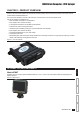
IC18 SPRAYER JOB COMPUTER U S E R Software version 1.
COPYRIGHTS © 2012 TeeJet Technologies. All rights reserved. No part of this document or the computer programs described in it may be reproduced, copied, photocopied, translated, or reduced in any form or by any means, electronic or machine readable, recording or otherwise, without prior written consent from TeeJet Technologies. TRADEMARKS Unless otherwise noted, all other brand or product names are trademarks or registered trademarks of their respective companies or organizations.
ISOBUS Job Computer : IC18 Sprayer Table of Contents CHAPTER 1– PRODUCT OVERVIEW OPTIONAL SYSTEM COMPONENTS 1 1 CHAPTER 2 – GETTING STARTED 3 START UP 3 APPLICATION MODE 3 PAGE LAYOUT AND NAVIGATION 4 Home Screen....................................................................................................................................................................4 Transport Mode.......................................................................................................
ISOBUS Job Computer : IC18 Sprayer Nozzle Preset Setup.......................................................................................................................................................16 Nozzle Preset.......................................................................................................................................................16 Nozzle Type..............................................................................................................................
ISOBUS Job Computer : IC18 Sprayer Target Rate Percentage Increase/Decrease.................................................................................................................................29 Regulation Valve Manual Open/Close..........................................................................................................................................29 Target Rate.......................................................................................................................
ISOBUS Job Computer : IC18 Sprayer CHAPTER 1– PRODUCT OVERVIEW Congratulations on the purchase of your new IC18 ECU built on the ISOBUS architecture. This IC18 unit has the capability of either sprayer or NH3 control when integrated into the implement of either capability. When used within the guidelines of this manual, the IC18 controller will be a reliable application tool. This manual covers the Sprayer functions of the IC18 ECU. For NH3 functions, see manual number 98-05230.
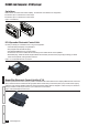
ISOBUS Job Computer : IC18 Sprayer Switchbox Manual section control with remote master capibility. The switchboxs are available in two configurations.
ISOBUS Job Computer : IC18 Sprayer CHAPTER 2 – GETTING STARTED • A firm touch is required when selecting a screen icon. • Settings are NOT automatically saved when selected. The ACCEPT KEY must be selected to save the setting. Select the ESCAPE KEY to escape without saving settings and return to the previous menu. • The console needs to be cycled off and back on when changing or attaching equipment to the system.
ISOBUS Job Computer : IC18 Sprayer PAGE LAYOUT AND NAVIGATION The Master Screen gives access to the systems currently available on your VT. From the Master Screen, the Home Screen gives access to the IC18’s available functions. Home Screen The Home Screen gives access to the IC18’s available functions: Operation Mode, Transport Mode and Main Setup. Figure 2-4: Home Screen - Crop Sprayer Mode Operation Mode Regulation Mode Current selection, Auto/Manual, is highlighted with a green dot.
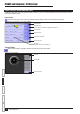
ISOBUS Job Computer : IC18 Sprayer Operation Mode Information on the Operation screen will vary depending on the parameters set by the user and the OEM. Figure 2-6: Operation Mode Screen Overview Applied Area Applied Volume Active Trip Count Number Alert Warning Cnt 5 Speed/Application Information 5.2 Remaining Tank Contents km/h Density Flow Based or Pressure Based 4070 l Target Rate Indicator Application Rate Target Rate Percentage Increase/Decrease 1.14 ha Cnt 5 5.
ISOBUS Job Computer : IC18 Sprayer Main Setup Mode The main setup menu contains six options. Each of these options either directly access settings or additional menus. Figure 2-7: Main Setup Screen Home Key Back One Screen Forward One Screen Up One Selection Down One Selection Master Screen Key The table below outlines the additional menus and directs you to the setup pages for further information.
ISOBUS Job Computer : IC18 Sprayer Main Setup Menu Icons and Section Overviews Figure 2-8: Enter Selection Screens Selection Slide Bar with Decrease One Selection and Increase One Selection Arrows Accept Key Escape Key Number Pad Close Number Pad Key Range Maximum Range Minimum Zoom In Key Zoom Out Key Open Number Pad Key Available Selections Up One Selection Accept Key Escape Key Description Section or Icon Description Accept Key Accepts the new selection Slider Close Number Pad Key Minimizes the
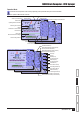
ISOBUS Job Computer : IC18 Sprayer CHAPTER 3 – MAIN SETUP IN SPRAYER MODE Main Setup Mode configures the Counters, Job Parameters, Machine, User Interface, Communication and Help options. NOTE: The menu structure on your display might vary from the one displayed in this User Manual depending on the virtual terminal being used.
ISOBUS Job Computer : IC18 Sprayer ►User Interface – used to allow the operator to select the system virtual terminal (VT), switchbox pairing, BoomPilot ECU pairing and soft key numbering as well as view serial numbers and ECU identification numbers: ►Communication – used to establish the IC18's ability to communicate with an external computer: ►Help – allows the operator to choose between Diagnostics and the About screen: ◄ Diagnostic – used to troubleshoot input/output of the controller (sensor or actuat
ISOBUS Job Computer : IC18 Sprayer COUNTERS The Counters Menu provides an overview of various system counters including Trip Counters, Campaign Counters and Total Counters. From this screen one can also Export Counters. | Counters | Job Parameters MAIN SETUP MENU | Machine | User Interface | Communication Trip Campaign Total Export Counters 1. From the Main Setup Screen , select COUNTERS. 2.
ISOBUS Job Computer : IC18 Sprayer Trip Counters Trip Counters displays information regarding area, distance, time and amount applied. The trip that is active is displayed/active on the Operations Screen. Figure 3-5: Trip Counters Menu Active Trip Counter One of up to ten (10) Active Trip Counters can be selected to view the desired trip information. The trip that is “active” is displayed/active on the Operation Screen. • To select the Active Trip Counter, use the number pad or slide bar.
ISOBUS Job Computer : IC18 Sprayer Total Counters Total Counters displays information regarding area, amount applied, and time for all Figure 3-9: Total Counters activity. Total Counters can only be cleared in the OEM menu. Area Counter Displays total applied coverage area for all trips. Volume Counter Displays total volume of material applied during all trips. Time Counter Displays total time traveled for all trips.
ISOBUS Job Computer : IC18 Sprayer JOB PARAMETERS Job Parameters configures application settings. Options include Active Trip Counter, Preset Application Rates and Nozzle. | Counters 1. From the Main Setup Screen MAIN SETUP MODE MENU STRUCTURE | Job Parameters | Machine | User Interface , select JOB PARAMETERS. | Communication | Help Figure 3-11: Job Parameters NOTE: Settings are NOT automatically saved when selected. The ACCEPT KEY must be selected to save the setting.
ISOBUS Job Computer : IC18 Sprayer MACHINE Machine configures machine settings. Options include Filling, Operation, Implement Parameters, Calibrations, Alarm Configurations and OEM.
ISOBUS Job Computer : IC18 Sprayer Density Factor Density Factor establishes the weight per volume setting based on the type of fertilizer being used. • To select the Density Factor, use the number pad or slide bar. The fertilizer’s ability to flow is affected by a number of factors. These factors may vary with each batch and it may change due to weather (humidity, etc.). In order to accommodate for this, the job computer uses a density factor to compensate for the nature of the applied fertilizer.
ISOBUS Job Computer : IC18 Sprayer Implement Parameters Implement Parameters establishes the following: ►Section Width – sets the spraying width during application. ►Nozzle Preset Setup – where up to five (5) sets of nozzle options can be established to set the nozzle type, size, low/high pressure limit, reference flow and reference pressure. ►Regulation Parameters – where adjustments to the valve calibration, nozzle spacing and regulations mode can be established.
ISOBUS Job Computer : IC18 Sprayer When “General” nozzle type is selected and a establised nozzle size is selected, the Low Pressure Limit, High Pressure Limit, Reference Flow and Reference Pressure fields will be automatically set with the standard settings for the specific nozzle chosen. These setting can be manually adjusted. Low Pressure Limit Low Pressure Limit establishes the limit for the lowest allowed operating pressure for the selected nozzle type.
ISOBUS Job Computer : IC18 Sprayer Regulation Parameters Regulation Parameters establishes adjustments to the valve calibrations, nozzle spacing and regulations mode. NOTE: Adjusting the Valve Calibration settings involves significant changes and adjustments should therefore be made in small steps. Figure 3-22: Regulation Parameters Valve Calibration, Rough Rough regulation value calibration allows you to regulate the setting of the regulating valve to accommodate different application needs.
ISOBUS Job Computer : IC18 Sprayer Calibrations Figure 3-23: Calibrations Calibrations establishes either manual or automatic settings of the sensors. NOTE: For specific calibration options to appear, a specific sensor needs to be installed. Sensor availability is activated on the Sensor Presence screen in the OEM section. Implement Speed Sensor The Implement Speed Sensor establishes the wheel pulses over a specified distance. This value can be established manually or calibrated automatically.
ISOBUS Job Computer : IC18 Sprayer Alarm Configurations Alarm Configurations establishes alarms on or off as well as sets their trigger level. Figure 3-26: Alarm Configurations CAN Speed Source Timeout CAN Speed Source Timeout establishes how long the system can operate after the CAN speed source input is lost before the alarm is triggered. • To select the CAN Speed Source Timeout time, use the number pad or slide bar.
ISOBUS Job Computer : IC18 Sprayer USER INTERFACE User Interface allows the operator to select the system virtual terminal (VT), switchbox pairing, BoomPilot ECU pairing and soft key numbering as well as view serial numbers and ECU identification number. | Counters 1. From the Main Setup Screen MAIN SETUP MODE MENU STRUCTURE | Job Parameters | Machine | User Interface , select USER INTERFACE.
ISOBUS Job Computer : IC18 Sprayer COMMUNICATION Communication establishes the IC18's ability to communicate with an external computer. | Counters 1. From the Main Setup Screen MAIN SETUP MODE MENU STRUCTURE | Job Parameters | Machine | User Interface | Communication | Help Figure 3-31: Communication , select COMMUNICATION. HELP The Help menu allows the operator to choose between Diagnostics and the display of information about serial number, CAN BUS information, etc.
ISOBUS Job Computer : IC18 Sprayer Diagnostic Diagnostic is used to troubleshoot input/output of the controller (sensor or actuator). Figure 3-33: Diagnostic ►Test Input – displays the input high and low values on the installed sensors. ►Test Output – sets the Liquid Valve PWM Dutycycle percentage as well as if Liquid Valve Direction, Master Valve, Fill Valve and Section Valves 1-9 are on or off. ►VT – provides information regarding the virtual terminal controller.
ISOBUS Job Computer : IC18 Sprayer VT Data The Virtual Terminal (VT) menu provides information regarding the virtual terminal Figure 3-36: VT Data controller (i.e., address version, etc.). • If more terminals/controllers are used, switch between these by pressing the GO TO NEXT VT KEY . • Press the DELETE OBJECT POOL KEY to delete saved information on the VT. This forces the VT to upload all information from the IC18 on the next power cycle.
ISOBUS Job Computer : IC18 Sprayer CHAPTER 4 – OPERATION MODE The Operation Screen accesses the working aspects of the IC18 including boom section control, rate control and trip/count/ application information. NOTE: Settings are automatically saved when selected. NOTE: The menu structure on your display might vary from the one displayed in this User Manual depending on the virtual terminal being used.
ISOBUS Job Computer : IC18 Sprayer OPERATION MODE OVERVIEW Information on the Operation screen will vary depending on the parameters set by the user and the OEM. Figure 4-2: Operation Mode Screen Overview Applied Area Applied Volume Active Trip Count Number Alert Warning Cnt 5 Speed/Application Information 5.2 Remaining Tank Contents km/h Density Flow Based or Pressure Based 4070 l Target Rate Indicator Application Rate Target Rate Percentage Increase/Decrease 1.14 ha Cnt 5 5.
ISOBUS Job Computer : IC18 Sprayer Keys Descriptions Icon Description Home Key Press to return to the Home Screen Start/Stop Key Press to start or stop application Information Key Press to toggle between display modes Boost/Step Percentage Increase/Decrease Keys Press to establish the required boost percentage step, i.e.
ISOBUS Job Computer : IC18 Sprayer Section or Icon Description Flow Based or Pressure Based Icons These symbols will only appear if both a flow sensor and a pressure sensor are installed. Flow Based - displayed if a regulation is based on flow Pressure Based - displayed if regulation is based on pressure. Density Displays a “D” to the left of the tank icon if the density is set to “Fertilizer” instead of water.
ISOBUS Job Computer : IC18 Sprayer Home Screen The Home Screen gives access to the IC18’s available functions: Operation Mode, Transport Mode and Main Setup. • To view the Home Screen, select HOME KEY in the top right corner of any screen. Figure 4-4: Home Screen Home Key on Operation Mode Screen Cnt 1 0.0 km/h 0 l 1 3 11 0.
ISOBUS Job Computer : IC18 Sprayer Target Rate Preset Application Rates define up to five (5) target rates of product being applied per hectare/acre. These settings will set the same for all active trips. Target rates set to “0.0” will not be included in the toggle preset target rate options on the Operation Screen or Home Screen. If a switchbox is being used to control the boom sections, current target application rate can be set on the Operation Screen.
ISOBUS Job Computer : IC18 Sprayer BOOM SECTIONS Boom Sections displays the active and inactive boom sections as well as if they are on (spray is blue) or off (spray is gray). Figure 4-9: Boom Sections The color on the boom sections indicates the color of the selected nozzle type. Cnt Established Nozzle Sizes and Colors Size Color Size Color 01 Orange 05 Brown 015 Green 06 Grey 02 Yellow 08 White 025 Purple 10 Light Blue 03 Blue 15 Light Green 04 Red 20 Black 1 0 l 0.0 0.
ISOBUS Job Computer : IC18 Sprayer Start/Stop Application When a switchbox is not connected for boom section control, starting/stopping application is controlled using the Start/Stop Key. Without Switchbox • To start or stop the application, press the START/STOP KEY . Figure 4-13: Spraying Stopped Cnt With Switchbox 5.0 If a switchbox is being used to control the boom sections, starting/stopping application will be controlled by the switchbox.
ISOBUS Job Computer : IC18 Sprayer INFORMATION KEY Information Key toggles the Speed/Application Information section on the Operation Screen between the display modes. • Vehicle speed • Volume applied per minute • Projected area per hour to be covered based on current speed, target rate and tank level • Projected total area remaining to be covered based on current target rate and current tank level Figure 4-18: Information Key Cnt Vehicle speed 1 0 l 0.0 0.
ISOBUS Job Computer : IC18 Sprayer TRANSPORT MODE While in Transport Mode, all operation functions are locked off and cannot be activated. Transport Mode displays the speed in analogue mode. Figure 4-19: Transport Mode Home Key ►Gives access to the IC18’s available functions: Operation Mode, Transport Mode and Main Setup Speedometer Master Screen Key ►Gives access to the systems currently available on your VT OVERVIEW GETTING STARTED SETUP OPERATION APPENDIX 34 www.teejet.
ISOBUS Job Computer : IC18 Sprayer APPENDIX A - FACTORY SETTINGS & RANGES JOB PARAMETERS Description Factory Setting Range User Setting Active Trip Counter 1 1 - 10 1 2 3 4 5 6 7 8 9 10 Preset Application Rate #1 Preset Application Rate #2 Preset Application Rate #3 0.0 GPA (US) 0.0 l/ha 0.0 GPA (UK) 0.0 - 700.6 (US) 0.0 - 6553 0.0 - 583.
ISOBUS Job Computer : IC18 Sprayer Implement Parameters Regulation Parameters Description Factory Setting Range Valve Calibration, Rough 19 1 - 19 Valve Calibration, Fine 9 1-9 Nozzle Spacing 19.7 in 50 cm 1.0 - 787.4 1.0 - 1999.9 Regulation Mode Flow Based Pressure Based Flow Based Description Factory Setting Range Section Width 118 in.
ISOBUS Job Computer : IC18 Sprayer Calibrations Implement Speed Sensor Description Factory Setting Range/Options Pulses per Distance 0 0 - 33445 Description Factory Setting Range/Options CAN Speed Source Timeout 4 sec 0 - 999 Active Trip Count Imformtaion Off Off On Tank Content Minimum 0 GAL (US) 0 liters 0 GAL (UK) 0 - 2641 (US) 0 - 9999 0 - 2199 (UK) Description Factory Setting Range/Options Use Perferred VT Off Off On Pair with Switchbox Auto Auto None <> Pair w
I C18 S P R AYE R J O B CO M P U T E R U S E R Software Version 1.