M at r i x ® P r o BoomPIlot® Setup Guide For use with software version 2.0x and 2.5x. Refer to the Matrix Pro GS User Manual for details on setup with software version 3.x.
Table of Contents General Matrix® Pro Information 1 Setup Option Information........................................................................................................................................................1 Drop Down Menu Selections..................................................................................................................................................1 Keyboard Entry Screen.....................................................................................
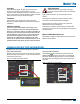
Matrix® Pro Copyrights Safety Information © 2013 TeeJet Technologies. All rights reserved. No part of this document or the computer programs described in it may be reproduced, copied, photocopied, translated, or reduced in any form or by any means, electronic or machine readable, recording or otherwise, without prior written consent from TeeJet Technologies. TeeJet Technologies is not responsible for damage or physical harm caused by failure to adhere to the following safety requirements.
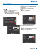
BoomPilot® Keyboard Entry Screen Press the KEYPAD icon to use a numeric keypad to enter a value. Press Clear to erase the existing value. Press the ACCEPT icon to save the settings or the CANCEL icon to leave the keypad without saving Unit Setup Mode Availability Vehicle Type Vehicle – Direction to Boom Distance to Boom Figure 1-3: Example of Keyboard # Implement Front Wheel – Delay Off Enable Spray Width Overlap Delay On Ant Height Dir to Boom 12.
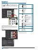
Matrix® Pro GPS is Required GPS is used to configure GPS Type and GPS Port. NOTE: These settings are required for auto steering and tilt sensor operation, as well as proper implement operation. 1. Press CONFIGURATION side tab . 2. Press GPS . 3.
BoomPilot® GPS Status External Receiver Minimum Configuration Requirements GPS Status displays information regarding data rates, number of satellites in view, and satellite quality and ID. 1. Press Information . 2. View data including: ◄GGA/VTG (Data Rates) – the number of GPS positions per second. ◄Num Sats – the number of GPS satellites in view (minimum of 4 are required for DGPS) ◄HDOP – a measure of satellite geometry strength in the horizontal plane. A HDOP value of less than 2 is preferred.
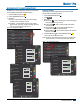
Matrix® Pro BoomPilot Configuration The Matrix Pro is used to configure the vehicle and its implements. To access Matrix Pro BoomPilot configuration options: 1. Press UNIT SETUP bottom tab . 2. Press CONFIGURATION side tab . 3. Select from: ►Vehicle – used to establish vehicle type, antenna height, direction to boom and distance to boom. ►Implement – used to establish number of boom sections, guidance width, spray width, overlap percentage, implement delay on time and implement delay off time.
BoomPilot® Vehicle Type Vehicle Type selects the type of vehicle steering that most closely represents your vehicle. Default is Front Wheel. 1. Press DOWN arrow 2. Select vehicle type. to access the list of options. 1. Press DOWN arrow to access the list of options. 2.
Matrix® Pro Implement Implement – Single Section Setup Settings will vary depending on if a SmartCable or Section Driver Module (SDM) is present. NOTE: If a SmartCable or Section Driver Module (SDM) is present, refer to “SmartCable or Section Driver Module Setup” to view setup steps. Implement Setup is used to establish the various settings associated with the vehicle’s implement. Speed Out / Sense In cable Implement for a single boom is used to establish guidance width and spray width.
BoomPilot® Guidance Width Spray Width Guidance Width establishes the width between the guidelines. Range is 34.0 - 2952.7 inches / 0.9 - 75.0 meters. Default is 60 feet / 18.29 meters. Spray Width establishes the width of the implement. Range is 34.0 2952.7 inches / 0.9 - 75.0 meters. Default is 144.0 inches (12 feet) / 3.66 meters. 1. Press the KEYPAD icon . 2. Use the entry screen to establish the guidance width. 1. Press the KEYPAD icon . 2. Use the entry screen to establish the spray width.
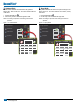
Matrix® Pro Implement – SmartCable or Section Driver Module Setup Implement is used to establish number of boom sections, guidance width, spray width, overlap percentage, implement delay on time and implement delay off time. NOTE: If a SmartCable or Section Driver Module (SDM) is not present, refer to “Single Section Setup” to view setup steps. 1. Press CONFIGURATION side tab . 2. Press Implement . 3.
BoomPilot® # Number of Boom Sections Spray Width Number of Boom Sections establishes the number of available boom sections. If a SmartCable or Section Driver Module (SDM) is present, 1 to 6 or 1 to 15 section widths can be entered (depending on which SmartCable or Section Driver Module (SDM) is detected). Default is 1. Spray Width establishes the width of each implement section. Range is 0.0 - 2952.7 inches / 0.0 - 75.0 meters. Default per section is 144.0 inches / 3.66 meters.
Matrix® Pro Figure 1-24: Delay On Overlap Overlap determines the amount of overlap allowed when the each boom section is turned on and off using Automatic Boom Section Control. Default is 50%. 1. Press DOWN arrow 2. Select: ►0% ►50% ►100% Figure 1-23: Overlap Config->Implement (2) Overlap to access the list of options. 50% Delay On 1.00 s Delay Off 1.00 s Delay On Time (s) Config->Implement (2) Overlap 50% 0% Delay On 50%1.00 s 100% Delay Off 1.
BoomPilot® BoomPilot Operation SmartCable or SDM Single Section If a SmartCable or Section Driver Module (SDM) is present, , Automatic BoomPilot is used to set BoomPilot to Off/Manual . or All On NOTE: GPS is unavailable when the BOOMPILOT icon is grey BoomPilot status bar icon will be Off/Manual . . If a SmartCable or Section Driver Module (SDM) is not present, please refer to Single Section to view example. If Work On/Off Switch is in the “On” position, improper application may occur.
Matrix® Pro BoomPilot Status BoomPilot Status displays information regarding the current status of the BoomPilot system. to view the number of sections. 1. Press BOOMPILOT STATUS icon -13 Mark A 7.2 mph BoomPilot Status Red = Off/Manual Green = Automatic Yellow = All On No icon = Single Boom Section (no SmartCable or SDM installed on system) Num Sections: 15 Appendix - Factory Settings & Ranges Vehicle Setup Settings Description Factory Setting Range Vehicle Type Front Wheel Antenna Height 12.
M at r i x ® P r o BoomPilot® Setup Guide This guide contains the instructions to setup the automatic boom section control (ABSC) or BoomPilot options on the vehicle through the Matrix Pro console. Please review this manual thoroughly after completing the installation process. 1801 Business Park Drive Springfield, Illinois 62703 USA www.teejet.