
User's Manual


the Transmit Interval time. A value of 0 for this parameter will disable measurements in
between the Transmit Interval. The units for this parameter are in seconds, with default set
to 0.
•
Temperature Change, defined as a percentage change in the Thermistor resistance value
(i.e. temperature) detected by the sensor. A Delta Temp alarm will be generated within the
PC Software if a Sensor reading taken at a Measure Interval is more than Temperature
Change percent from the prior Transmit Interval value. The units for this parameter are
Percent (%), with the default value set to 0.
Usage
THe MDT/Sensors will come with Batteries installed. With the Configuration Tool running on the
PC and the Base or Access Point on and connected to a PC or the Internet, the user will press
and hold the button near the LED window until the LED starts to flash. It will flash slowly at
first, then rapidly flash when a Beacon is seen (from a Repeater or Base/AP), then finally
illuminates for 10 seconds when it successfully communicates with the network.
If configuration changes are required, the case can be opened and the Serial header inserted
into J4 (with the black/green lead toward the center of the board). Once changes are made, a
“reset” command is issued to restart the MDT/Sensor. All changes are stored in non-volatile
memory and will survive a battery change or power off.
Button Usage (for MDT/Sensor and Repeater)
When a unit is off, press and hold for three or four seconds to turn on. LED starts to flash
When unit is on, press and hold for three or four seconds to turn off. LED will be off
A single press can indicate the state of the unit
Constant on LED for 10 seconds means unit successfully communicating to network
Single LED flash indicates the unit is on but not communicating with the network
Double LED flash indicates the unit is OFF
A double press when the unit is on and Connected will trigger an immediate data transmission
Device Placement
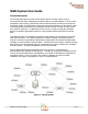
With the Base Unit plugged into the PC and the Database software running, the repeater
backbone can be placed. Start with units closer to the Base/AP, and use the LED feedback
indication to verify the range is acceptable. At first just the minimum numbers of repeaters can
be placed, with additional repeaters added to fill in holes after MDT/Sensor placement.
THIS DEVICE COMPLIES WITH PART 15 OF THE FCC RULES. OPERATION IS
SUBJECT TO THE FOLLOWING TWO CONDITIONS:
(1) THIS DEVICE MAY NOT CAUSE HARMFUL INTERFERENCE, AND
(2) THIS DEVICE MUST ACCEPT ANY INTERFERENCE RECEIVED, INCLUDING
INTERFERENCE THAT MAY CAUSE UNDESIRED OPERATION.
WAM User's Guide.pages! 3 of 4