Installation and maintenance manual COCINAS CRISTAL-GAS CG.1 4G / CG.1 3G. 1P CG Lux-60 4G. / CG Lux-70 4G. / CG Lux-70 4G AI AL CG Lux-70 5G. / CG Lux-60 4G. Al AL / CG Lux-70 5G.
User’s Guide to this Instruction Manual Dear Customer, Safety Instructions Thank you for choosing a TEKA hob. Before using your hob for the first time, please read the installation and connection instructions. We are sure that our product will fully satisfy your requirements. This modern, functional and practical appliance has been built using top quality materials which are subjected to strict quality controls throughout the manufacturing process.
Contents Introduction Description of the Appliance Page 4 4 Installation Positioning of the hobs Positioning of the oven Anchoring of the hob Connecting the hob to the oven or the control panel Gas Connection Electrical Connection Gas transformation 9 9 10 10 Technical Information Dimensions and powers Technical Data Rating Plates 16 16 18 20 Use and Maintenance Special requirements before first use Component Par ts of Gas Burners Lighting of Burners Switching on Electric Hotplates Components of a Sa
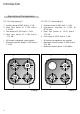
Introduction Description of the Appliance CG. 1 4G (see drawing 1) CG.1 3G. 1P. (see drawing 2) 1 Auxiliary burner of 860 Kcal/h - 1 kW. 2 Semi fast burner of 1,500 Kcal/h 1.75 kW. 3 Fast burner of 2,550 Kcal/h - 3 kW 4 Semi fast burner of 1,500 Kcal/h 1.75 kW. 1 Auxiliary burner of 860 Kcal/h - 1 kW. 2 High -powe r hotp late of 1,5 00 W, Ø 145 mm. 3 Semi fast burner of 1,500 Kcal/h 1.75 kW. 4 Fast burner of 2,550 Kcal/h - 3 kW. • All burners incorporate a pan suppor t.
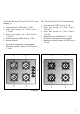
CG-Lux-60 4G. and CG Lux-60 4G AI AL (see drawing 3) 1 Fast burner of 2,580 Kcal/h - 3 kW. 2 Semi fast burner of 1,500 Kcal/h 1.75 kW. 3 Semi fast burner of 1,500 Kcal/h 1.75 kW. 4 Auxiliar y burner of 860 Kcal/h - 1 kW. 5 Burner controls. CGC 4G and CGC 4G AI AL (see drawing 4) 1 Fast burner of 2,580 Kcal/h - 3 kW. 2 Semi fast burner of 1,500 Kcal/h 1.75 kW. 3 Semi fast burner of 1,500 Kcal/h 1.75 kW. 4 Auxiliary burner of 860 Kcal/h - 1 kW. • All burners incorporate a pan suppor t.
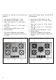
CG-Lux-70 5G., and CG Lux -70 5G AI AL (See drawing 5) CG-Lux-70 5G TR and CG Lux -70 5G AI TR AL (See drawing 6) 1 Fast burner of 2,580 Kcal/h - 3 kW. 2 Fast burner of 2,580 Kcal/h - 3 kW. 3 Semi fast burner of 1,500 Kcal/h 1.75 kW. 4 Semi fast burner of 1,500 Kcal/h 1.75 kW. 5 Auxiliary burner of 860 Kcal/h - 1 kW. 6 Burner controls. 1 Fast burner of 2,580 Kcal/h - 3 kW. 2 Triple ring burner of 3,000 Kcal/h 3.5 kW. 3 Semi fast burner of 1,500 Kcal/h 1.75 kW. 4 Semi fast burner of 1, 500 Kcal/h 1.75 kW.
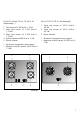
CG-Lux-70 4G and CG Lux -70 4G AI AL (See drawing 7) 1 Fast burner of 2,580 Kcal/h - 3 kW. 2 Semi fast burner of 1,500 Kcal/h 1.75 kW. 3 Semi fast burner of 1,500 Kcal/h 1.75 kW. 4 Auxiliar y burner of 860 Kcal/h - 1 kW. 5 Burner controls. CG-Lux-75 2G AI TR AL (See drawing 8) 1 Triple ring burner of 3,010 Kcal/h 3.5 kW. 2 Triple ring burner of 3,010 Kcal/h 3.5 kW. 3 Burner controls. • All burners incorporate a pan suppor t. • Maximum calorific power: 6,020 Kcal/h 7 kW.
CG-Lux-86 3G AI TR AL (See drawing 9) CG-Lux-86 2G 1P AI TR AL (See drawing 10) 1 Triple ring burner of 3,010 Kcal/h 3.5 kW. 2 Triple ring burner of 3,010 Kcal/h 3.5 kW. 3 Semi fast burner of 1,500 Kcal/h 1.75 kW. 4 Burner controls. 1 • All burners incorporate a pan suppor t. • Maximum calorific power: 7,520 Kcal/h 8.75 kW. 1 3 2 • All burners incorporate a pan suppor t. • Maximum calorific power: 6,020 Kcal/h 7 kW. • Maximum electric power: 1,500 Watts.
Installation Important INSTALLATION AND ADJUSTMENT MUST BE CARRIED OUT BY AUTHORISED TECHNICAL PERSONNEL ACCORDING TO THE APPLICABLE INSTALLATION REGULATIONS. A Positioning of the hobs Depending on the model to be installed an aperture will be made in the worktop, of the dimensions specified in the drawing 11. A template is included in the packaging of models CG.1 4G. and CG.1 3G. 1P. for the correct sizing of the aperture for these two hob models.
Positioning of the oven In the cases of the models CG.1 4G and CG.1 3G 1P, the clamps must be fitted as shown in the picture 13, depending on the thickness of the furniture. See the applicable manual. Anchoring of the hob Once the hob position has been dimensioned, the seal (J) must be affixed to the lower part of the cooker. This is fastened by means of four clamps (G), each of which has two tabs (P) which are inserted in the apertures (O) in the hob until they click into place.
Hob models CG-Lux-75 2G and CG-Lux-86 3G are installed in the same way as the CGC 4G AI AL, except for the staples which are geometrically dif ferent. The installation of these hobs must be carried out in the way shown in the drawing 15, depending on the thickness of the work top. B A 20 mm. 30 mm. 40 mm. Drawing 15 A Seal C B Work top D Fastening clip D If the unit below the hob is to be used to store products it must be situated at a distance of at least 10 cm below the hob.
Rear view of the Control Panel: 1 Fix the hob knob covers on the oven according to the oven instructions manual. Fix the knob covers included with the hob and remove those for the oven. This hob comes complete with knob covers for all TEKA ovens except for models RT-600 and RT-800. For these two models, order the knob covers in your nearest TEKA establishment or official technical service. 3 2 Gas Connection Drawing 18 1 Flexible Power Cable. 2 Connector. 3 Power Unit Protective Casing.
TEKA will not accept responsability for faults or damage caused by incorrect or defective instalation. Once the gas connetion has been made the air tightness of the installation mus be checked. If the check is made using air, the testing pre s s u re must be no greater than 200 g/cm 2 . To avoid causing damage to the hob during installation when tightenig the gas pipe connection nut, a maximum grip torque of 350 kg.f.cm must be used.
Gas transformation Important! The transformation of the appliance to use a d i ff e rent gas to that for which it has been sold must only be carried out by a qualified technician. Information for the Technical Service: in the event of conversion of the type of gas or pressure in the appliance, the new regulation label must be placed over the existing one, in order to identify the new characteristics after the changeover.
• In order to access the screw which graduates the gas flow through the taps in hob CGC 4G AI AL, remove the screws that fix the cover protecting the taps to the case and lift the cover. Others hobs • Remove the tap controls by pulling them upwards strongly. • Light the burners at their minimum setting. • Use a small screw driver to remove the screw on the right or centre of the plug of the gas key (turn left for a big flame and right for a small flame).
Technical information Dimensions and powers Models Dimensions in mm Length Width Depth Glass thickness Worktop hob dimensions mm. Length Width 3.5 kW Triple ring gas burner 3 kW fast burner 1.75 kW semi fast burner 1 kW auxiliary burner 1,000 W electric hotplate Ø 145 mm. 1,500 W electric hotplate Ø 145 mm. 1,500 W electric hotplate Ø 180 mm. CG.1 4G CG.1 3G. 1P. CG Lux-60 4G AI AL CG Lux-60 4G. CGC 4G CGC 4G AI AL CG Lux-70 4G.
Models Dimensions in mm Length Width Depth Glass thickness Worktop hob dimensions mm. Length Width 3.5 kW Triple ring gas burner 3 kW fast burner 1.75 kW semi fast burner 1 kW auxiliary burner 1,000 W electric hotplate Ø 145 mm. 1,500 W electric hotplate Ø 145 mm. 1,500 W electric hotplate Ø 180 mm. CG Lux-70 CG Lux-70 CG Lux-70 CG Lux-70 CG Lux-70 CG Lux-75 CG Lux-86 CG Lux-86 4G AI AL 5G. 5G AI AL 5G AI TR AL 5G.
Technical Data COMMON CHARACTERISTICS TO THE ELECTRIC HOTPLATES AND AUTOMATIC LIGHTING MODEL The supply voltage and frequency must be those indicated in the rating plate. The fire p rotection is of “X” type. The hob must be installed at over 15 cm away from the side walls. (See drawing 20). In the event of a hotplate being cracked the hob must be switched off at the mains. c) “This appliance must not be connected to a device for the evacuation of combustion products.
COMMON CHARACTERISTICS TO EVERY MODEL N.B.: All the hob models referred to in this manual have hot zones during or after their use and can cause burns. Care must be taken when handling these hobs before installation as there may be rough zones or corners which may be dangerous. Table 3 Burner Nominal calorific consumption Nominal consumptions* CCR CG Lux-60, CG Lux-70 CGC 4G, CG.1 4G and CG.1 3G.
TEKA INDUSTRIAL, S.A. SANTANDER - ESPAÑA CG.1 4G Mod. ∑ Qn (P.C.S.) 3 Clase CG LUX 60 4G Mod. ∑ Qn Nº 7.50 TEKA INDUSTRIAL, S.A. SANTANDER - ESPAÑA (P.C.S.) 3 Clase Nº 7.50 G-110 Vr 1.70 Nm3/h G-20 Vr 0.71 Nm /h G-110 Vr 1.70 Nm3/h G-20 Vr 0.71 Nm3/h G-130 Vr 1.05 Nm3/h G-25 Vr 0.83 Nm3 /h G-130 Vr 1.05 Nm3/h G-25 Vr 0.83 Nm3/h G-150 Vr 1.35 Nm3/h G-30 Mr 0.55 Kg/h G-150 Vr 1.35 Nm3/h G-30 Mr 0.55 Kg/h G-31 Mr 0.54 Kg/h G-31 Mr 0.54 Kg/h ES 3 FR Cat.
TEKA INDUSTRIAL, S.A. SANTANDER - ESPAÑA Mod. ∑ Qn (P.C.S.) CG LUX 70 5G 3 Clase Mod. ∑ Qn Nº 10.5 TEKA INDUSTRIAL, S.A. SANTANDER - ESPAÑA (P.C.S.) CG LUX 70 5G AI AL CG LUX 70 5G AI 3 Clase Nº 10.5 G-110 Vr 2.38 Nm3 /h G-20 Vr 1.00 Nm /h G-110 Vr 2.38 Nm 3/h G-20 Vr 1.00 Nm 3/h G-130 Vr 1.47 Nm3 /h G-25 Vr 1.16 Nm3/h G-130 Vr 1.47 Nm 3/h G-25 Vr 1.16 Nm 3/h G-150 Vr 1.89 Nm3/h G-30 Mr 0.77 Kg/h G-150 Vr 1.89 Nm3 /h G-30 Mr 0.77 Kg/h G-31 Mr 0.75 Kg/h G-31 Mr 0.
TEKA INDUSTRIAL, S.A. SANTANDER - ESPAÑA TEKA INDUSTRIAL, S.A. SANTANDER - ESPAÑA Mod. ∑ Qn (P.C.S.) CG LUX 70 4G AI AL CG LUX 70 4G AI 3 Clase ∑ Qn Nº 7.50 CGC 4G Mod. (P.C.S.) 3 Clase Nº 7.50 G-110 Vr 1.70 Nm3/h G-20 Vr 0.71 Nm3/h G-110 Vr 1.70 Nm3 /h G-20 Vr 0.71 Nm 3/h G-130 Vr 1.05 Nm3/h G-25 Vr 0.83 Nm3/h G-130 Vr 1.05 Nm 3/h G-25 Vr 0.83 Nm 3/h G-150 Vr 1.35 Nm3/h G-30 Mr 0.55 Kg/h G-150 Vr 1.35 Nm 3/h G-30 Mr 0.55 Kg/h G-31 Mr 0.54 Kg/h G-31 Mr 0.
TEKA INDUSTRIAL, S.A. SANTANDER - ESPAÑA Mod. CG LUX 70 5G AITR AL CG LUX 70 AI TR ∑ Qn Mod. CG LUX 75 2G AI TR AL CG LUX 75 2G AI TR ∑ Qn Nº 11 (P.C.S.) 3 Clase TEKA INDUSTRIAL, S.A. SANTANDER - ESPAÑA Nº 7 (P.C.S.) 3 Clase G-110 Vr 2.50 Nm3/h G-20 Vr 1.04 Nm /h G-110 Vr 1.59 Nm3/h G-20 Vr 0.66 Nm3/h G-130 Vr 1.54 Nm3/h G-25 Vr 1.22 Nm 3/h G-130 Vr 0.98 Nm3/h G-25 Vr 0.77 Nm3/h G-150 Vr 1.98 Nm3 /h G-30 Mr 0.81 Kg/h G-150 Vr 1.26 Nm3/h G-30 Mr 0.51 Kg/h G-31 Mr 0.
Use and Maintenance Special requirements before first use Before connecting the hob to the power supply check that the voltage and frequency are those indicated in the rating plate located on the lower par t of the hob. Remove the protecting plastic af fixed to the hob, if any. N.B. Each time you assemble a burner, check that all of its component parts fit together correctly. A badly positioned component may cause the hob glass to overheat. Lighting of burners For hobs models CGC 4G, CG.1 4G. and CG.
For hobs CG Lux-60, CG Lux-70, CG Lux-75 and CG Lux-86, which have automatic ignition and a safety feature, the following steps should be followed: (See drawing 23) • Check that the controls are in the correct position. • Open the mains connection gas tap or the gas bottle cock. • Press the burner control. • While keeping the burner control pressed, turn it as far as it will go until the gas ignites. Keep pressed for 5 to 10 seconds, in order to permit the safety thermocouple to be activated.
Use flat bottomed pans and check that they are placed correctly on the pan suppor t, in order to prevent pans from sliding when their contents star t to boil (do not use pans with concave or convex bases). The red-point hotplate (1,500 W) heats up especially quickly and at its maximum power during approximately the first five minutes. After this time its power drops to 500 W and it conser ves the same temperature.
Components of a Safety System On all the hobs which incorporate the safety feature (models with initials AL), the gas cutoff system is comprised formed by the following elements: (See drawing 26). G C F A • Safety tap • Safety thermocouple next to the burner • Thermocouple-tap connection B E D Drawing 26 The thermocouple sends an electrical signal to the tap, detecting the presence or absence of a flame at the burner.
Using your Hob • Do not use the glass surface as a storage area. • Do not put aluminium plates, tinfoil or plastics on the glass surface. • On hobs which have five burners, pans of l a rge diameters must always be placed on the central burner in order to prevent heat from being reflected onto the worktop. On hobs with four burners you should use the pan suppor t supplement with this type of pan.
Suggestions and Recommendations Hints for the Correct Usage of Burners • Do not use large burners with pans of small diameters as par t of the flame will be deflected around the outside of the pan, thus considerably reducing efficiency. (See drawing 29) A hob, in order to prevent deflected flames from damaging worktops with plastic surfaces. Hints for the Correct Usage of Electric Hotplates For maximum ef ficiency with electric hotplates, follow these guidelines: • Use pans with totally flat bottoms.
Reminder Do not use small pans on large burners, as the flame will be dissipated. Use appropriately sized pans for each burner, thus making the best use of the heat. Do not place pans unevenly on the pan support. Place the pan correctly over the centre of the burner. Do not use pans which reflect excessive heat downwards directly on the pan support. When using a griddle pan, stoneware pots or pans which reflect heat downwards, always use the pan support supplement.
Cleaning and Conservation For the correct conser vation of the hob glass it must be cleaned using the appropriate products and utensils and when the glass is cold. Cleaning is easier if it is done each time the hob is used, thus preventing the build-up of dir t. The cleaning of the hob glass will depend on its degree of dirtiness: • When the hob is only slightly dir ty and the dirt is not adhered, clean with a damp cloth and mild detergent.
Electric Hotplates (Mod. CG.1 3G. 1P.) Maintenance Before cleaning, disconnect the appliance from the mains supply. No part of this appliance requires period lubrication, though the gas tap cones should be kept clean and well greased. Electric hotplates should be cleaned with soapy water and a non-abrasive scourer.
Important If Something Doesn’t Work Before calling the Technical Service, make the following checks: Fault Possible Cause Neither the hob nor the pilot light works. The mains cable is not connected. No spark appears when the automatic ignition switch is pressed. Power is not reaching the plug. Solution Connect the mains cable. Check / repair the mains supply. A spark appears but the burner does not ignite. The sparking plug and the corresponding burner zone is dirty or coated with grease.
TEKA GROUP COUNTRY CITY COMPANY CC PHONE FAX Austria Belgium Chile China Czech Republic France Greece Hungary Indonesia Malaysia Wien Zellik Santiago de Chile Shanghai Brno Paris Athens Budapest Jakarta Kuala Lumpur 43 32 56 86 42 33 30 36 62 1 - 86680 - 20 2466 - 8740 2 - 273.19.45 21 - 6236 - 2375 05 - 4921 - 0479 1 - 4891 - 3788 10 - 9760283 1 - 354.21.10 21 - 39052 - 74 1 - 86680 - 82 2446 - 7687 2 - 273.10.88 21 - 6236-2379 05 - 4921 - 0479 1 - 4891 - 2973 10 - 9712725 1 - 354.21.