
User's Manual


GB
8
The glass covers can shatter when
they heat up. Turn off the burners before
closing the cover.
See the corresponding manual.
When the gap has been properly sized,
the sealing washer (J) should be put on
the part of the cooker.
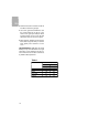
Position the clips (K) as shown in figure 2,
fastening them to the openings in the
lower part of the body using the metal thre-
aded screws provided (Ø 4.2 mm).
The clips (K) and the sealing washer (J)
are provided, and can be found in the pac-
kaging.
For worktop thicknesses of less than 30
mm., use the self-tapping screws (M) that
are provided as a fastening accessory - put
them into the clip’s round hole. This hole will
be threaded as the screw is inserted into it,
and this should be done before fixing the
clip to the worktop.
Connecting the hob to the gas mains
should be done in compliance with the
current installation standards and regula-
tions.
Ventilation slots should also be made at
the site in compliance with current norms.
The hob is provided with a threaded con-
nection 1/2” in diameter, in line with ISO
228-1. A Ø 10/12 mm copper pipe is provi-
ded as an accessory for welding the gas
inlet pipe.
Whenever the gas connection nut is remo-
ved, its washer should be changed.
In order that the hob is not damaged by
tightening the nut on the gas connection
pipe, a maximum torque of 350 cm * Kgf
should be applied.
When the gas connection has been made,
the installation should be checked to ensu-
re that it is completely sealed. If the check
is done using air, care should be taken that
the test pressure is no more than 200
gr./cm
2
. Where air is not available, soapy
water should be applied to ensure that
there are no leaks in the connections. Tes-
ting should never be done using a
flame.
When the hob has been installed, check
that the burner minimums are properly
fig. 2
Fixing the hob
Connecting the gas
Positioning the oven
20 mm
30 mm
40 mm