
Submittal Sheet
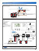

Below is a sample application drawing for this product. This application may include other tekmar products that are required
for installation. More sample applications can be found at www.tekmarcontrols.com.
Sample Electrical diagram
Sample Mechanical diagram
Product design, software and literature are Copyright © 20 by:
tekmar Control Systems Ltd. and tekmar Control Systems, Inc.
2 of 2
All specifications are subject to change without notice.
Printed in Canada. C 26 - 0/.
tekmar Control Systems Ltd., Canada, tekmar Control Systems, Inc., U.S.A.
261
070
C
R
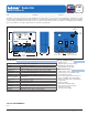
Boiler Control 261
Two Stage Boiler & Setpoint
Do not apply power
158033
1
Boiler
Demand L N NL 1 1 2 2 Sw
2
Boil Uno Com Boil Out Com
3 4
5
6
7
8
9 10 11
12 13
14
15 16
17
Power
Stage Stage
Advanced
Installer Off
Rotate
Item
Test
Made in Canada by
tekmar Control Systems Ltd.
Power: 120 V ±10% 50/60 Hz 1300 VA
Relays: 240 V (ac) 10 A 1/3 hp, pilot duty 240 VA
Demands: 20 to 260 V (ac) 2 VA
Terminal Unit Setpoint
Fire Delay Setpoint Demand
Boiler Demand
Signal wiring must be
rated at least 300 V
Use supply wires suitable for
120°F (50°C) above ambient
Setpoint
Demand
H11068
ROOM
-
Set to desired room temp.
OUTDR DSGN
-
Set to coldest (design)
outdoor temp.
Terminal Unit Set to
High Mass Radiant ------- 1
Low Mass Radiant ------- 2
Fan Coil ------------------ 3
Convector ---------------- 4
Radiator ------------------ 5
Baseboard --------------- 6
Setpoint - Set to desired setpoint temp.
Refer to brochure for more information
Installer Instructions
To increase or decrease the
building temperature.
• Press the Item, , buttons
simultaneously for 1 sec. to
enter the ADJUST menu
• Use the, , buttons to adjust
the ROOM setting
Display defaults back to VIEW
menu after 20 sec.