
Application Brochure

© 2013 284_A - 02/13 6 of 12
S4
S3
S5
P1 P2 P3 P4
P5
S2
S6
S1
284
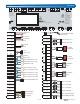
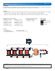
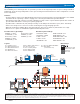
S1 = DHW Sensor
S2 = Boiler Inlet Sensor
S3-S6 - Boiler Outlet Sensors
P1-P4 = Boiler Pumps
P5 = DHW Recirculation Pump
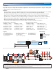
Application A 284-3 Mechanical
Description
Four two-stage non-condensing boilers are operated to provide a fixed setpoint temperature for a dedicated DHW load.
The DHW recirculation pump can optionally be operated on a schedule to save energy.
Concept Drawing: This is only a concept drawing, not an engineered drawing. It is not intended to describe a complete system, nor any particular system. It is up to the
system designer to determine the necessary components for and configuration of the particular system being designed, including additional equipment, isolation relays
(for loads greater than the control’s specified output ratings), and any safety devices which in the judgement of the designer are appropriate, in order to properly size,
configure and design that system and to ensure compliance with building and safety code requirements.
Features:
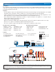
The boiler plant is sequenced to obtain maximum efficiency based on the boiler types & target temperatures. For detailed
information about sequencing, rotation & staging, refer to the 284_D Installation & Operation Manual.
Boiler ∆T monitoring is available when using optional boiler outlet sensors (S3 to S6) & boiler inlet sensor (S2).
•
•
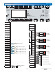
ENABLE (1) = AUTO
CONDENSE (1) = NO
Boil TYPE (1) = 2STG
ENABLE (2) = AUTO
CONDENSE (2) = NO
Boil TYPE (2) = 2STG
ENABLE (3) = AUTO
CONDENSE (3) = NO
Boil TYPE (3) = 2STG
ENABLE (4) = AUTO
CONDENSE (4) = NO
Boil TYPE (4) = 2STG
Essential Source (#) Settings:
APP MODE = DDHW
AUX RELAY = DHWR
Essential System Settings:
Legend
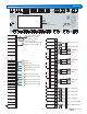
DIP Settings:
External Flow Proof / Off
External C.A. Proof / Off
Off / Exercise
Setback / Off