
Application Brochure

9 of 12 © 2013 284_A - 02/13
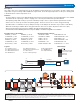
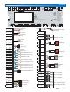
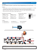
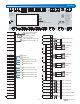
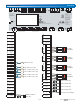
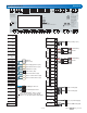
Application A 284-4 Electrical
*Up to 24 tekmarNet
®
devices can be
connected to each bus. Note that all
4 buses use the boiler water temperature.
tN2
C
tN2 Wiring Center 313
tN4
C
tN4 Gateway 482 / 483
L
N
L
N
Mod
Stage 1
T
T
+
-
Modulating
Boiler
Boiler 1 Pump (P2)
Boiler 2 Pump (P3)
Indirect DHW Pump (P4)
115 V (ac) Power Supply
Flow Proof
Call
C.A. Proof
Call
Heat
Call
IDHW
Call
Setpoint
Call
20V dc Out
5V dc Out
V dc (+) In
Gnd (-)
EMS (+)
Out
Boil Sup
Boil Ret
DHW
Com
Com (-)
mA (+) In
1
2
3
4
Primary
Pump P1
Primary
Pump P2
47
48
49
50
5
6
7
8
Auxiliary
43
44
Bus b
Boiler
Boiler
Boiler
Boiler
tN4
C0
Bus 1 tN4
C1
Bus 2 tN4
C2
Bus 3 tN4
C3
32
33
34
35
36
37
38
39
Modbus
A
B
40
41
9
10
11
12
13
14
15
16
17
18
19
20
21
22
Vent
Boil In
Com
Boil 1 Out
Boil 2 Out
Boil 3 Out
Boil 4 Out
Com
23
24
25
26
27
Gnd
42
28
29
30
Alert
45
46
Boiler 1
Pump
Boiler 2
Pump
75
76
77
78
Boiler 3
Pump
Boiler 4
Pump
Power
In
79
80
81
82
IDHW
Pump
85
86
53
54
Stage 1
Stage 2
Boiler 1
51
52
55
56
N
83
84
59
60
Stage 1
Stage 2
Boiler 2
57
58
61
62
65
66
Stage 1
Stage 2
Boiler 3
63
64
67
68
71
72
Stage 1
Stage 2
Boiler 4
69
70
73
74
L
Com
31
Primary Pump 1 (P1)
Modulating
Boiler
Boiler Supply Sensor (S2)
Boiler Return Sensor (S3)
DHW Sensor (S4)
Boiler 1 Outlet Sensor (S6)
Boiler 2 Outlet Sensor (S7)
Boiler Inlet Sensor (S5)
Vent Sensor (S8)
Outdoor
Sensor (S1)
Mod
+
-
Mod
+
-
Mod
+
-
Mod
+
-
Mod
Stage 1
T
T
+
-
L
N
L
N
L
N
1 2345
Temperature Sensors - Do Not Apply Power
tekmarNet Communication
C3C2C0 C1
H7019A
Boiler 1
75 76
Pump
Boiler 2
77 78
Pump
Boiler 3
79 80
Pump
Boiler 4
81 82
Pump Pump
Power In
L N
IDHW
Alert
45 46
Auxiliary
43 44
Pump
47 48
P1
Pump
Primary Primary
49 50
P2
85 8683 84
20V
11
dc
5V
dc
Out In Out
Flow Sensor
Pressure
Sensor
In In
Vdc
14
(+) (+)
Gnd
15
(-) (-)
mA
12 13
(+)
EMS
16
Out
17
Boil
Sup
18
Com
19
Boil
Ret
Boil
In
20
DHW
21
Com
22
Vent
23 24
25
Boil
1
Out
26
Boil 2
Out
27
ComCom
28
Com
31
Boil 3
Out
29
Boil 4
Out
30
tN4
32 33
Bus b
tN4
34 35
Bus 1
tN4
36 37
Bus 2
tN4
38 39
Bus 3
Boiler Boiler Boiler Boiler
Flow Proof
1
2
Call
C.A. Proof
34
Call
Heat
56
Call
IDHW
7
8
Call
Setpoint
910
Call
AB
40 41
BACnet Modbus
42
Gnd
External Flow Proof / Off
External C.A. Proof / Off
Off / Exercise
Setback / Off
51 52
Mod
Boiler 1
53 54
Stage 1 Stage 2
55 56
+
-
Mod Stage 1 Stage 2
+
-
Mod Stage 1 Stage 2
+
-
Mod Stage 1 Stage 2
+
-
57 58
Boiler 2
59 60
61 62 63 64
Boiler 3
65 66
67 68 69 70
Boiler 4
71 72
73 74
tektra 1056-01
For product literature:
www.tekmarControls.com
Caution! Disconnect All
Power before Opening
Designed and
assembled in Canada
Meets Class B: Canadian
ICES & FCC Part 15
Input Power:
115 V (ac) ±10% 60 Hz, 18 VA
Primary Pump Relays:
230 V (ac) 10 A, 1/2 hp
Boiler & IDHW Pumps:
230 V (ac) 5 A, 1/3 hp
Auxiliary & Alert Relays:
230 V (ac) 5 A, 1/6 hp
Boiler Stage Relays:
24 V (ac) 5 A
Calls: 24 V (ac) or Short
Signal wiring must be
rated at least 300 V.
Boiler Control 284
Four tN4, BAS, Four Boiler, DHW & Setpoint
Manual
Override
Home