- Data Brochure D 364 Universal Reset Control 364 07/01 The Universal Reset Control 364 is designed to maximize the comfort and efficiency provided by a hydronic heating system. The control automatically adjusts the boiler and mixed loop water temperatures that are delivered to the heating system by using outdoor reset. For a mixing device, the 364 can use either a variable speed injection pump or a floating action mixing valve.
Introduction This brochure is organized into four main sections. They are: 1) Sequence of Operation, 2) Installation, 3) Control Settings, and 4) Troubleshooting. The Sequence of Operation section has six sub-sections. We recommend reading Section A: General of the Sequence of Operation, as this contains important information on the overall operation of the control. Then read the sub sections that apply to your installation.
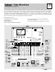
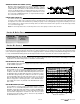
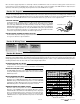
Display Number Field Item Field Displays the current value of the selected item Displays an abbreviated name of the selected item Mix Demand Boiler Demand DHW Demand Setpoint Demand WWSD Min / Max Melting Menu Field Displays the current menu Status Field Displays the current status of the control's inputs, outputs and operation Buttons Selects Menus, Items and adjusts settings Symbol Description Open / Close Displays when the actuator is opening or closing the mixing valve.
Sequence of Operation Section A Section B Section C Section D Section E Section F General Boiler Zones Mixing Zones Page 4-5 Page 5-6 Domestic Hot Water/Setpoint Page 6-9 Snow Melting Page 12-14 Boiler Operation Page 15-16 Page 9-11 Section A: General POWERING UP THE CONTROL When the Universal Reset Control 364 is powered up, the control displays the control type number in the LCD for 2 seconds. Next, the software version is displayed for 2 seconds.
WARM WEATHER SHUT DOWN (WWSD) When the outdoor air temperature rises above the WWSD setting, the 364 turns on the WWSD pointer in the display. When the control is in Warm Weather Shut Down, the Mix Demand and Boiler Demand pointers are displayed if there is a demand. However, the control does not operate the heating system to satisfy these demands. The control does respond to a DHW demand and / or setpoint demand and operates as described in Section C.
WARM WEATHER SHUT DOWN (WWSD) When the outdoor air temperature rises above the WWSD setting, the 364 turns on the WWSD pointer in the display. When the control is in Warm Weather Shut Down, the Boiler Demand pointer is displayed if there is a demand. However, the control does not operate the heating system to satisfy this demand. The control does respond to either a DHW demand or a setpoint demand and operates as described in section C.
Internal Demand (tekmar Sensor) If the DHW SENS item is set to DHW, the 364 looks for a DHW sensor connected to the DHW and the Com terminals (28 and 27). The DHW TANK setting is used to set the desired indirect DHW tank temperature. When the temperature at the DHW sensor drops 3°F (1.5°C) below the DHW TANK setting, The DHW Demand pointer turns on in the LCD and the control operates as described below. An advantage to using the DHW sensor is that the control can display the current DHW TANK temperature.
Boiler and Mixing Priority (DHW PRI = B+M) It can be selected that the DHW tank has priority over the boiler and mixing zones. If this option is chosen, the mixing device is throttled back and the boiler system pump (P2) turns off on a call for DHW. DHW PRIORITY OVERRIDE CONDITIONAL DHW PRIORITY If the boiler supply temperature is maintained at or above the required temperature during DHW generation, this indicates that the boiler has enough capacity for DHW and possibly heating as well.
Once the boiler supply temperature is sufficiently reduced, the DHW device shuts off. Then the heating system is turned on for a period of time to prevent the building from cooling off excessively. After a period of heating, if the DHW demand is still present, the 364 shuts off the boiler system pump (P2) and provides heat to the DHW tank once again. Section C4: Setpoint The 364 can handle loads which are high temperature loads connected to the boiler loop that are not heating loads or DHW.
MIXING INDOOR (MIX INDR) The MIX INDR is the room temperature used in the original heat loss calculations for the building. This setting establishes the beginning of the Characterized Heating Curve for the mixing zones. MIXING MINIMUM (MIX MIN) The MIX MIN is the lowest temperature that the control is allowed to use as a MIX TRG temperature.
Section D3: Mixing Demands EXTERNAL MIXING DEMAND An external mixing demand allows for the use of a conventional thermostat system for zoning. An external mixing demand is generated by applying a voltage between 24 and 240 V (ac) across the Mix Demand terminals (1 and 2). Once voltage is applied, the Mix Demand pointer is displayed in the LCD. If the 364 is not in WWSD, the 364 closes the Mix Sys Pmp P3 contact. The mixing system pump segment is displayed in the LCD.
Section E: Snow Melting Section E Section E2 Section E3 Section E4 General With Slab Sensor Without Slab Sensor Snow Melting Enable Section E1: General The Universal Reset Control 364 is capable of controlling a single zone snow melting system. In order to provide the best control of the snow melting system, the 364 should be equipped with an optional tekmar Slab Sensor and an optional Universal Sensor 071 that measures the slab return temperature.
RUNNING TIME (RUN TIME) The run time is the length of time the snow melting system operates once the slab has reached the melting temperature. During the time that the slab is approaching the melting temperature, the run time does not decrease. Once the slab has reached the melting temperature, the run time begins counting down. When the run time reaches 0:00 as displayed by the SNOWMELT item in the View menu, the 364 has finished melting.
Section E3: Without Slab Sensor In cases where a slab sensor has not been or cannot be installed in the snow melting slab, it is possible for the Universal Reset Control 364 to operate the snow melting system. This mode of operation is not recommended since the control can no longer regulate the slab temperature. Instead, the control supplies a calculated mixed supply water temperature to the slab.
Section F: Boiler Operation Section F1 Section F2 Section F3 Boiler Supply Sensor Boiler Return Sensor No Boiler Sensor Section F1: Boiler Supply Sensor BOILER SENSOR ON THE SUPPLY (Boil SENS = SUP) The boiler sensor can be located on the boiler supply if the 364 is the only control that is operating the boiler. When in the supply mode, the 364 determines the required operating temperature for the boiler supply and cycles the Boiler contact to maintain the correct supply water temperature.
BOILER OPERATION When the 364 determines boiler operation is required, the Boiler contact terminals (15 and 16) close. While the Boiler contact is closed, the burner segment in the LCD is displayed. BOILER PURGE (PURGE P1) After all of the demands are satisfied, the 364 continues to operate the primary pump (P1, terminal 8) for a period of time. The length of time that the primary pump continues to run is adjustable (PURGE P1).
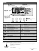
STEP THREE ————— ROUGH-IN WIRING All electrical wiring terminates in the control base wiring chamber. The base has standard 7/8” (22 mm) knockouts which accept common wiring hardware and conduit fittings. Before removing the knockouts, check the wiring diagram and select those sections of the chamber with common voltages. Do not allow the wiring to cross between sections as the wires will interfere with safety dividers which should be installed at a later time.
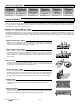
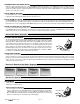
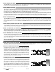
DHW Demand To generate a DHW demand, a voltage between 24 V (ac) and 240 V (ac) must be applied across the Setp / DHW and the Com Dem terminals (5 and 4). 5 4 Com Setp/ Dem DHW 24 to 240 V (ac) Setpoint Demand To generate a setpoint demand, a voltage between 24 V (ac) and 240 V (ac) must be applied across the Setp / DHW and the Com Dem terminals (5 and 4). 15 16 Output Connections Boiler Boiler Contact The Boiler terminals (15 and 16) are an isolated output in the 364.
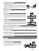
Sensor and Unpowered Input Connections 27 28 29 Do not apply power to these terminals as this will damage the control. Out Com DHW Outdoor Sensor Connect the two wires from the Outdoor Sensor 070 to the Com and Out terminals (27 and 29). The outdoor sensor is used by the 364 to measure the outdoor air temperature. 24 25 26 Boiler Sensor Com Connect the two wires from the Boiler Sensor 071 to the Com and Boil terminals (24 and 26).
DHW Sensor A DHW Sensor 071 can connect to the DHW input. Connect the two wires from the sensor to the Com and DHW terminals (27 and 28). STEP FIVE —————— 27 28 Com DHW TESTING THE WIRING Each terminal block must be unplugged from its header on the control before power is applied for testing. To remove the terminal block, pull straight down from the control.
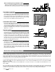
Test The Outputs 6 7 Power L N Primary Pump (Prim P1) If a primary pump is connected to the Prim P1 terminal (8), make sure that power to the terminal block is off and install a jumper between the Power L and Prim P1 terminals (7 and 8). When power is applied to the Power L and Power N terminals (7 and 6), the primary pump should start. If the pump does not turn on, check the wiring between the terminal block and pump and refer to any installation or troubleshooting information supplied with the pump.
Connecting The Control 6 Make sure all power to the devices and terminal blocks is off, and remove any remaining jumpers from the terminals. N 7 Power L 8 Prim P1 9 10 Boil Sys Pmp P2 Reconnect the terminal blocks to the control by carefully aligning them with their respective headers on the control, and then pushing the terminal blocks into the headers. The terminal blocks should snap firmly into place.
Access Levels The Universal Reset Control 364 comes with four Access Level settings. These Access Levels restrict the number of Menus, Items and Adjustments that can be accessed by the user. The four access levels are Limited (LTD), User (USER), Installer (INST) and Advanced (ADV). The access level of the control is found in the Miscellaneous (Misc) menu when the Lock / Unlock DIP switch is set to the Unlocked position. In the Advanced access level, all of the control settings are available to the user.
364 View Menu (1 of 2) Access Level © 2001 Se ct LT ion D U SE IN R S AD T V Item Field Description Range Current outdoor air temperature as measured by the outdoor sensor. -67 to 149°F (-55 to 65°C) D3 Target room air temperature. “---” denotes no heat is required. MIX 10K = INDR ---, 35 to 100°F (2 to 38°C) D3 Measured room air temperature at the indoor sensor.
364 View Menu (2 of 2) Se ct LT ion D U SE IN R S AD T V Item Field Access Level Description Range F1 Target boiler supply is the temperature the control is currently trying to maintain at the boiler sensor ±1/2 of the differential. Boil SENS = SUP ---, 1 to 255°F (-17 to 124°C) F1 Current boiler supply water temperature as measured by the boiler sensor. Boil SENS = SUP -31 to 266°F (-35 to 130°C) F2 Current boiler return water temperature as measured by the boiler sensor.
364 Adjust Menu (2 of 5) Access Level © 2001 Se ct LT ion D U SE IN R S AD T V Item Field Description Range E1 The maximum ∆T for the snow melting slab. DIP switch = Snow Melting 10 to 70°F, OFF (-6 to 39°C, OFF) Default = 40°F (22°C) E1 The Cold Weather Cut Off temperature for the snow melting system. DIP switch = Snow Melting OFF, -30 to 50°F (OFF, -34 to 10°C) Default = 10°F (-12°C) D1 The desired room air temperature for the mixing zones.
364 Adjust Menu (3 of 5) Se ct LT ion D U SE IN R S AD T V Item Field Access Level Description Range D1 The maximum supply temperature for the mixing system. 80 to 210°F, OFF (27 to 99°C, OFF) Default = 140°F (60°C) B1 D1 The design outdoor air temperature used in the heat loss calculation for the heating system. -60 to 50°F (-51 to 10°C) Default = 10°F (-12°C) D2 The type of mixing device that is to be used in the heating system.
364 Adjust Menu (4 of 5) Access Level © 2001 Se ct LT ion D U SE IN R S AD T V Item Field Description Range F1 The time delay that the control can expect between the time the boiler contact closes and the burner fires. Boil SENS = SUP 0:00 to 3:00 min Default = 0:10 min F1 The thermal mass characteristics of the boiler that is being used. Boil SENS = SUP LITE, MED, HEVY Default = MED F1 The differential that the control is to use when it is operating the boiler.
364 Adjust Menu (5 of 5) Se ct LT ion D U SE IN R S AD T V Item Field Access Level The frequency with which the control will exercise the pumps and valves that are operated by the control. A Actual Setting Range Description 30 to 240 hr Default = 70 hr 364 Misc (Miscellaneous) Menu (1 of 1) Description Range LT D U SE IN R S AD T V Item Field Access Level The units of measure that all of the temperatures are to be displayed in by the control.
Testing the Control The Universal Reset Control 364 has a built-in test routine which is used to test the main control functions. The 364 continually monitors the sensors and displays an error message whenever a fault is found. See the following pages for a list of the 364’s error messages and possible causes. When the Test button is pressed, the test light is turned on. The individual outputs and relays are tested in the following test sequence.
Troubleshooting When troubleshooting any heating system, it is a good idea to establish a set routine to follow. By following a consistent routine, many hours of potential headaches can be avoided. Below is an example of a sequence that can be used when diagnosing or troubleshooting problems in a hydronic heating system. Establish the Problem Establish the problem. Get as much information from the customer as possible about the problem.
364 Error Messages (1 of 3) Error Displayed Description of Error The control was unable to store a piece of information into its EEPROM. This error can be caused by a noisy power source. The control will display the error message and will continue to operate as normal. Pressing either the Menu or Item button will clear this error. The control was unable to read a piece of information stored in the Adjust menu.
364 Error Messages (2 of 3) Error Displayed Description of Error The control is no longer able to read the mix return sensor due to a short circuit. The control continues to operate without ∆T protection of the slab. Locate and repair the problem as described in the Data Brochure D 070. To clear the error message from the control after the sensor has been repaired, press either the Menu or Item button. The control is no longer able to read the mix return sensor due to an open circuit.
364 Error Messages (3 of 3) Error Displayed Description of Error The control is no longer able to read the DHW sensor due to a short circuit. In this case, the control ceases DHW operation. Locate and repair the problem as described in the Data Brochure D 070. To clear the error message from the control after the sensor has been repaired, press either the Menu or Item button. The control is no longer able to read the DHW sensor due to an open circuit. In this case, the control ceases DHW operation.
Notes 35 of 36 © 2001 D 364 - 07/01
Technical Data Universal Reset Control 364 Mixing, Boiler & DHW Literature Control Packaged weight Dimensions Approvals Ambient conditions — — — — — — Power supply Relays Var. Pump Demands Sensors included — — — — — Optional devices — D 364, A 364’s, D 070, D 001, U 364, E 021, E 003 Microprocessor PID control; This is not a safety (limit) control 3.9 lb.