
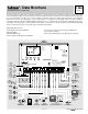
Installation

© 2001 D 364 - 07/01 10 of 36
MIXING INDOOR (MIX INDR)
The MIX INDR is the room temperature used in the original heat loss calculations for the building. This setting establishes the
beginning of the Characterized Heating Curve for the mixing zones.
MIXING MINIMUM (MIX MIN)
The MIX MIN is the lowest temperature that the control is allowed to use as a MIX TRG temperature. During mild conditions, if the
364 calculates a MIX TRG temperature that is below the MIX MIN setting, the MIX TRG temperature is adjusted to match the MIX
MIN setting. During this condition, if the mixing supply temperature is near the MIX MIN setting, the Min / Max pointer turns on in
the LCD when either the MIX TRG temperature or the MIX SUP temperature is being viewed.
If an indoor sensor is used and the 364 is operating at the MIX MIN temperature, the mixing system pump (P3) is cycled using
Pulse Width Modulation (PWM) with a 15 minute cycle length. By cycling the mixing system pump (P3) and controlling the flow of
supply water, the control provides an average supply water temperature to the mixing system. This average temperature is equal to
the original MIX TRG. This minimizes overheating of the zone while the control is operating at the MIX MIN temperature.
MIXING ROOM (MIX ROOM)
The MIX ROOM is the desired room temperature for the mixing zones and it provides a parallel shift of the Characterized Heating
Curve. The room temperature desired by the occupants is often different from the designed indoor temperature (MIX INDR). If
the room temperature is not correct, adjusting the MIX ROOM setting increases or decreases the amount of heat available to the
building.
MIXING TARGET TEMPERATURE (MIX TRG)
The MIX TRG temperature is determined from the Characterized Heating Curve settings and the outdoor air temperature. The
control displays the temperature that it is currently trying to maintain as the mixing supply temperature. If the control does not pres-
ently have a requirement for heat, it displays “---“ in the LCD.
MIXING SYSTEM PUMP (P3) OPERATION
The mixing system pump (P3) contact (terminals 11 and 12) closes whenever there is mixing demand and the 364 is not in WWSD.
After the mixing demand is removed, the Mix Sys Pmp P3 contact remains closed for an additional 20 seconds. During WWSD, the
mixing system pump (P3) is operated based on the EXERCISE setting in the Adjust menu.
BOILER MINIMUM PROTECTION (Boil MIN)
The 364 is capable of providing boiler protection from cold mixing system return water temperatures. If the boiler water temperature
is cooler than the Boil MIN setting while the boiler is firing, the 364 reduces the output from the mixing device. This limits the amount
of cool return water to the boiler and allows the boiler water temperature to recover. This feature can only be used if the Boil SENS
item is set to SUP or RET.
MIXING DEVICE SELECTION (MIXING)
The 364 can supply a lower water temperature to part of the heating system by varying the speed of an injection pump or modulat-
ing a mixing valve. This selection is made under the MIXING item in the Adjust menu.
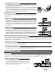
VARIABLE SPEED INJECTION (VAR)
A standard wet rotor circulator is connected to the 364 on the Cls / Var
terminal (19). The 364 increases or decreases the power output to the
circulator when there is mix demand. The circulator speed varies to
maintain the correct mixed supply water temperature at the mix supply
sensor. For correct sizing and piping of the variable speed injection
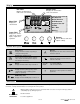
driven circulator, refer to essay E 021. A visual indication of the cur-
rent variable speed output is displayed in the LCD in the form of a seg-
mented bar graph. Two small indicators at the top of the graph indicate
whether the output is increasing or decreasing.
FLOATING ACTION (FLOT)
A floating action actuator motor is connected to the 364 on the Opn
and Cls / Var terminals (18 and 19). The 364 pulses the actuator motor
open or close to maintain the correct supply water temperature at the
mix supply sensor when there is a mix demand. The mixing valve that
the actuator is connected to can be either a 2-way, 3-way or 4-way
valve. A visual indication as to whether the control is currently open-
ing or closing the mixing valve is displayed in the LCD with the words
Open and Close. Also, a visual indication of the current position of the
valve is displayed in the LCD in the form of a segmented bar graph.
Section D2: Mixing Devices