
Installation

© 2001 D 364 - 07/01 2 of 36
This brochure is organized into four main sections. They are: 1) Sequence of Operation, 2) Installation, 3) Control Settings, and
4) Troubleshooting. The Sequence of Operation section has six sub-sections. We recommend reading Section A: General of the
Sequence of Operation, as this contains important information on the overall operation of the control. Then read the sub sections that
apply to your installation.
The Control Settings section (starting at DIP Switch Settings) of this brochure describes the various items that are adjusted and
displayed by the control. The control functions of each adjustable item are described in the Sequence of Operation.
Reference Material: Essay E 021: Mixing Methods and Sizing of Variable Speed Injection Pumps
Essay E 003: Characterized Heating Curves and Reset Ratios
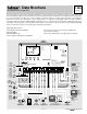
The 364 uses a Liquid Crystal Display (LCD) as the method of supplying information. You use the LCD in order to setup and monitor
the operation of your system. The 364 has four push buttons (Menu, Item, ▲, ▼) for selecting and adjusting settings. As you program
your control, record your settings in the Adjust menu table which is found in the second half of this brochure.
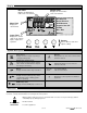
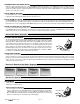
Menu
All of the items displayed by the control are organized into various menus. These
menus are listed on the left hand side of the display (Menu Field). To select a menu,
use the Menu button. By pressing and releasing the Menu button, the display will
advance to the next available menu. Once a menu is selected, there will be a group of
items that can be viewed within the menu.
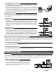
Item
The abbreviated name of the selected item will be displayed in the item field of the
display. To view the next available item, press and release the Item button. Once
you have reached the last available item in a menu, pressing and releasing the Item
button will return the display to the first item in the selected menu.
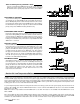
Adjust
To make an adjustment to a setting in the control, begin by selecting the appropriate
menu using the Menu button. Then select the desired item using the Item button.
Finally, use the ▲, and / or ▼ button to make the adjustment.
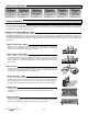
Additional information can be gained by observing the Status field of the LCD. The status field will indicate which of the control’s
outputs are currently active. Most symbols in the status field are only visible when the View menu is selected.
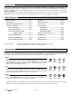
Table of Contents
User Interface
Introduction
Table of Contents ...............................................pg 2
User Interface .....................................................pg 2
Description of Display Elements .....................pg 3
Sequence of Operation .....................................pg 4
Section A: General .....................................pg 4
Section B: Boiler Zones .............................pg 5
Section C: Domestic Hot Water
(DHW) / Setpoint .......................pg 6
Section D: Mixing Zones ............................pg 9
Section E: Snow Melting ............................pg 12
Section F: Boiler Operation .......................pg 15
Installation ..........................................................pg 16
DIP Switch Settings ...........................................pg 22
Access Levels ....................................................pg 22
Control Settings
View Menu ...................................................pg 23
Adjust Menu ................................................pg 24
Miscellaneous Menu ................................. pg 28
Testing and Troubleshooting .......................... pg 29
Error Messages ..................................................pg 31
Technical Data ................................................... pg 36
Limited Warranty .............................................. pg 36
Menu Item
Menu Item
Menu Item