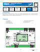
- Data Brochure D 421 Mixing Reset Module 421 1 Information Brochure 2 Application Brochure Choose controls to match application 08/07 3 Design your mechanical applications Rough-in Wiring 4 5 Wiring Brochure Wiring and installation of specific control Rough-in wiring instructions Data Brochure Control settings and sequence of operation 6 Job Record Record settings & wiring details for future reference Introduction The Mixing Reset Module 421 provides outdoor reset to a hydronic heating sys
Table of Contents Table of Contents ...........................................................2 Outdoor Reset ...................................................... 11 Display and DIP Switches ..............................................2 Mixing Operation .................................................. 13 Dip Switch Settings ................................................2 Boiler Temperature Control .................................. 14 Access Level .............................................
Boiler Sup / Ret Off / Flushing Use the Boiler Sensor Supply / Return DIP switch to select the location of the boiler sensor. The Off / Flushing DIP switch selects whether the control operates a Flushing feature. Heating systems that use potable water require periodic flushing to prevent the water from stagnating. • If the boiler sensor is located on the supply, this DIP switch should be set to Sup. The 421 is the control that determines the boiler water temperature.
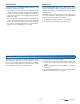
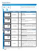
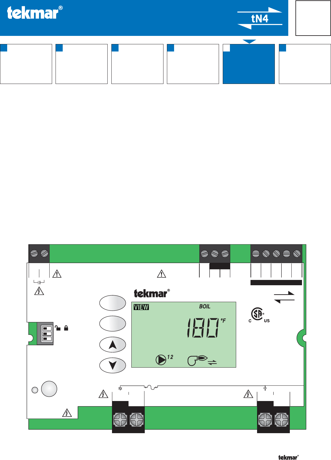
Display Symbols Description S Menu Field Item Field Displays the current menu Displays an abbreviated name of the selected item Status Field Number Field Displays the current status of the control’s inputs, outputs and operation. Most symbols in the status field are only visible when the VIEW Menu is selected Displays the current value of the selected item Symbols Description PUMP Displays when the mixing pump is in operation. °F, °C, %, HOURS, MINUTES Units of measurement.
User Interface Adjusting a Setting Use the User Interface available on the Liquid Crystal Display (LCD) to setup and monitor the operation of the system. Use the four push buttons to the left of the LCD (Menu, Item, Up, Down) to select settings. As you enter settings, record the settings in the Job Record J 421. To adjust a setting: 1. Select the appropriate menu using the Menu button. 2. Select the item using the Item button. 3. Use the Up or Down button to make the adjustment.
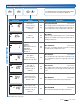
Display Menus View Menu (1 of 1) The View menu items display the current operating temperatures and status information of the system. VIEW MENU Item Field Range Access Description -76 to 149°F (-60.0 to 65.0°C) InS Ad SECTION B OUTDOOR Current outdoor air temperature as measured by the outdoor sensor. -22 to 266°F (-30.0 to 130.0°C) InS Ad SECTION B MIX SUPPLY Current mix supply water temperature as measured by the mix supply sensor.
Adjust Menu (1 of 2) The Adjust Menu items are the programmable settings used to operate the mechanical equipment. ADJUST MENU Item Field Range Access Description -60 to 45°F (-51.0 to 7.0°C) Default = 10°F (-12.0°C) InS Ad OUTDOOR DESIGN SECTION B The design outdoor air temperature used in the heat loss calculations for the heating system. Typically set to the temperature of the coldest day of the year.
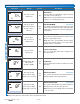
Adjust Menu (2 of 2) Item Field Range 30 to 230 seconds Default = 105 OFF, 80 to 180°F (OFF, 26.5 to 82.0°C) Default = 140°F (60.0°C) Au, 2 to 42°F (Au, 1 to 23.5°C) Access Description Ad MIX MOTOR The time that the actuating motor requires to operate from fully closed to fully open. Note: This item is only available when the Mix Mode setting is set to floating action (FLt).
Misc (Miscellaneous) Menu (1 of 1) The Miscellaneous Menu Items set control and display options such as access level and temperature units. MISC MENU Item Field Range Access Description InS (Installer) Ad (Advanced) InS Ad °F, °C Default = °F InS Ad UNITS Select temperature units between Fahrenheit and Celsius. 0 to 24 Ad BUS 1 DEVICES Displays the number of devices on bus 1 (Mixing).
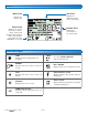
To enable Max Heat: HAZARD Access to the Test button requires the removal of the front cover and exposes hazardous voltage while the control is powered. Only trained, qualified and competent personnel should operate the Test button. Test Press and hold the Test button for more than 3 seconds and less than 6 seconds. If there is a demand for heat, the ‘TEST’ and ‘MAX’ segments are displayed on screen and the control will turn on all outputs for up to 24 hours.
Test Wait 3 seconds Hold for 6 seconds Test Sequence of Operation tekmarNet®4 Communication Section A tekmarNet®4 (tN4) communicates between tN4 devices (thermostats, Reset Module and Expansion Modules). Each tN4 device is connected to a tN4 communication bus using two wires. Each tN4 bus adjusts a single water temperature in the system using indoor temperature feedback. The Mixing Reset Module 421 allows for one tN4 bus. This allows you to control a system with one water temperature.
Terminal Unit There is a terminal unit setting for each tN4 bus. The Terminal Unit setting is found in the Adjust menu. Hydronic Radiant Floor (1) Terminal type 1 is a heavy, or high mass, hydronic radiant floor system. This type of a hydronic radiant floor is embedded in either a thick concrete or gypsum pour. This heating system has a large thermal mass and is slow acting. Hydronic Radiant Floor (2) Terminal type 2 is a light, or low mass, hydronic radiant floor system.
Terminal Unit Defaults When a terminal unit is selected, the control loads default values for the mix design, mix maximum supply, and mix minimum supply temperatures. The factory defaults can be changed to better match the installed system. • Locate the Mix terminal unit setting in the Adjust menu.
Mix Minimum Mix Maximum The Mix Minimum settings are the lowest temperature that the control is allowed to use as a mix target temperature. During mild conditions, if the control calculates a mix target temperature that is below the mix minimum setting, the mix target temperature is adjusted to match the mix minimum setting.
Boiler Enable Section E If the 421 is one of many controls that can call for heat to a single boiler or there is a boiler sequencer other than a tekmar Stager (Boiler Control 264, 265, 268), operating multiple boilers or multiple stages, then the boiler sensor must be located on the return pipe of the boiler(s). When the sensor is located on the return, the 421 provides a boiler enable.
Error Messages Local Errors and Device Errors Error messages are used to indicate a problem somewhere in the system. There are two types of error messages: Local Errors and Device Errors. A Local Error indicates an error specific to a device. For example, a thermostat with a sensor short circuit will show a Sensor Short Error on its display. No other devices will show this specific error (unless they also have a sensor short circuit).
Error Messages (1 of 2) Error Message Description ADJUST ERROR The control failed to read the Adjust menu settings, and reloaded the factory default settings. Operation stops until you check the Adjust menu settings. Note: To clear the error, the access level must be set to Advanced and the settings in the Adjust menu must be checked. MISCELLANEOUS ERROR The control failed to read the Miscellaneous menu settings, and reloaded the factory default settings.
Error Messages (2 of 2) Error Message Description BOILER SENSOR OPEN CIRCUIT Due to an open circuit, the control failed to read the boiler sensor. The control no longer controls the boiler. Instead, the control provides a boiler enable to the boiler’s aquastat or boiler control until the sensor is repaired. The control will not operate the boiler contact if the Boil Minimum setting is less than 100°F (38.0°C). Locate and repair the problem as described in the Data Brochure D 070.
Troubleshooting Symptom Possible Causes Corrective Action Trace wires from boiler contact to boiler Boiler does not fire when there Boiler contact is not connected to boiler thermostat connection. Use the Test is a mix demand. thermostat connection. sequence to check the boiler contact. Mixing valve will not open. No voltage present on actuator motor. Mix 1 Mode setting must be set to FLt. Boiler Return Protection.
Limited Warranty and Product Return Procedure Limited Warranty The liability of tekmar under this warranty is limited. The Purchaser, by taking receipt of any tekmar product (“Product”), acknowledges the terms of the Limited Warranty in effect at the time of such Product sale and acknowledges that it has read and understands same.