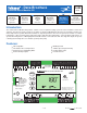
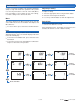
- Data Brochure D 422 Universal Reset Module 422 1 Information Brochure 2 Application Brochure Choose controls to match application 3 Design your mechanical applications 08/07 Rough-in Wiring 4 Wiring Brochure Wiring and installation of specific control Rough-in wiring instructions 5 Data Brochure Control settings and sequence of operation 6 Job Record Record settings & wiring details for future reference Introduction The Universal Reset Module 422 provides outdoor reset to a hydronic heat
Table of Contents Table of Contents ...........................................................2 Boiler Temperature Control .................................. 19 Display and DIP Switches ..............................................2 tekmar Stager Operation ...................................... 21 Dip Switch Settings ................................................2 Boil Enable ............................................................22 Access Level ...............................................
tN4 Boiler / Mix 2 Off / Flushing Use the tN4 Boiler / Mix 2 DIP switch to select whether the second tN4 bus (terminals 59-60) is to operate as a boiler water temperature or as a second mixing water temperature. The Off / Flushing DIP switch selects whether the control operates a Flushing feature. Heating systems that use potable water require periodic flushing to prevent the water from stagnating. • If set to Boiler, this creates a system with one boiler and one mix water temperature.
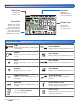
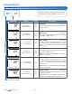
Display Symbols Description S Menu Field Item Field Displays the current menu Displays an abbreviated name of the selected item Status Field Number Field Displays the current status of the control’s inputs, outputs and operation. Most symbols in the status field are only visible when the VIEW Menu is selected Displays the current value of the selected item Symbols Description © 2007 PUMP Displays when the primary or mixing pump is in operation.
User Interface Adjusting a Setting Use the User Interface available on the Liquid Crystal Display (LCD) to setup and monitor the operation of the system. Use the four push buttons to the left of the LCD (Menu, Item, Up, Down) to select settings. As you enter settings, record the settings in the Job Record J 422. To adjust a setting: 1. Select the appropriate menu using the Menu button. 2. Select the item using the Item button. 3. Use the Up or Down button to make the adjustment.
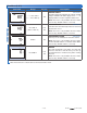
Display Menus View Menu (1 of 2) The View menu items display the current operating temperatures and status information of the system. Item Field Range Access Description -76 to 149°F (-60.0 to 65.0°C) InS Ad SECTION B OUTDOOR Current outdoor air temperature as measured by the outdoor sensor. -22 to 266°F (-30.0 to 130.0°C) InS Ad SECTION B MIX 1 SUPPLY Current Mix 1 supply water temperature as measured by the Mix 1 supply sensor.
View Menu (2 of 2) Item Field Range – – –, 35 to 230°F (– – –, 1.5 to 110.0°C) Access Ad Description BOILER TARGET SECTION C The boiler target is the temperature the control is currently trying to maintain at the boiler supply sensor. “– – –” is displayed when no heat is required for boiler zones. VIEW MENU Note: This item is only available when the Boiler Sensor Sup / Ret DIP switch is set to Sup. -22 to 266°F (-30.0 to 130.
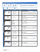
Adjust Menu (1 of 5) The Adjust Menu items are the programmable settings used to operate the mechanical equipment. Item Field Range Access -60 to 45°F (-51.0 to 7.0°C) InS Default = 10°F (-12.0°C) Ad VAr, FLt InS Default = VAr Ad ADJUST MENU 1 HRF1 2 HRF2 3 Fancoil 4 Fin-tube Convector 5 Radiator 6 Baseboard InS Ad OUTDOOR DESIGN SECTION B The design outdoor air temperature used in the heat loss calculations for the heating system.
Adjust Menu (2 of 5) Item Field Range 30 to 230 seconds Default = 105 1 HRF1 2 HRF2 3 Fancoil 4 Fin-tube Convector 5 Radiator 6 Baseboard Default = 1 40 to 100°F (4.5 to 38.0°C) Access Description Ad SECTION G MIX 1 MOTOR The time that the Mix 1 actuating motor requires to operate from fully closed to fully open. Note: This item is only available when the Mix 1 Mode setting is set to floating action (FLt). InS Ad Ad ADJUST MENU Default = 70°F (21.0°C) 70 to 220°F (21.0 to 104.
Adjust Menu (3 of 5) Item Field Range 40 to 100°F (4.5 to 38.0°C) Default = 70°F (21.0°C) 70 to 220°F (21.0 to 104.5°C) Default = 180°F (82.0°C) OFF, 80 to 180°F (OFF, 26.5 to 82.0°C) ADJUST MENU Default = 140°F (60.0°C) 120 to 225°F, OFF (49.0 to 107.0°C, OFF) Default = 200°F (93.5°C) 0:00 to 3:00 min Default = 0:10 min Au, 2 to 42°F (Au, 1 to 23.5°C) Access Description Ad SECTION B BOILER INDOOR The design indoor air temperature used in the heat loss calculation for the boiler zones.
Adjust Menu (4 of 5) Item Field Range Access Description SECTION C MINIMUM MODULATION The minimum percent modulation of the burner. 0 to 50% Default = 0% Ad Note: This item is only available when the Boiler Sensor Sup / Ret DIP switch is set to Sup, the Boiler On-Off / Mod DIP switch is set to Mod, and the tekmar stager DIP switch is set to OFF. MAXIMUM MODULATION SECTION C The maximum percent modulation of the burner.
Adjust Menu (5 of 5) Item Field Range 60 to 220°F (15.5 to 104.5°C) ADJUST MENU Default = 180°F (82.0°C) OFF, ON Default = OFF 40 to 100°F, OFF (4.5 to 38.0°C, OFF) Default = 70°F (21.0°C) 40 to 100°F, OFF (4.5 to 38.0°C, OFF) Access Ad Description SETPOINT OCCUPIED SECTION J The minimum boiler target temperature when a setpoint demand is present during the Wake and Occupied periods. Note: This item is only available when Setpoint Mode is set 1 through 4.
Misc (Miscellaneous) Menu (1 of 1) The Miscellaneous Menu Items set control and display options such as access level and temperature units. MISC MENU Item Field Range Access InS (Installer) Ad (Advanced) InS °F, °C InS Default = °F Ad Ad 0 to 24 Ad 0 to 24 Ad 0 to 24 Ad OFF, SEL Ad 422 InS Ad Description ACCESS LEVEL The access level of the control. The access column shows which items are visible in each access level.
Testing the Control The control has a built-in test routine that tests the main control functions. The control continually monitors the sensors and displays an error message whenever a fault is found. The individual outputs and relays are tested using a test sequence. Step 1 The Mix 1 device ramps up to 100% over 10 seconds or according to the motor speed setting. Step 2 The Mix 1 device ramps down to 0% over 10 seconds or according to the motor speed setting.
Max Heat Zone Test The control has a function called Max Heat. In this mode, the control turns on and operates the system up to the maximum set temperatures as long as there is a demand for heat. tN4 thermostats operate to meet the occupied setting +5°F (3°C). The control operates in this mode for up to 24 hours or until the Test button is pressed. Use this mode to run the circulators during system start-up to purge air from the piping.
Sequence of Operation tekmarNet®4 Communication Section A tekmarNet®4 (tN4) communicates between tN4 devices (thermostats, Reset Module and Expansion Modules). Each tN4 device is connected to a tN4 communication bus using two wires. Each tN4 bus adjusts a single water temperature in the system using indoor temperature feedback. The Universal Reset Module 422 allows for two tN4 buses. This allows you to control a system with two separate water temperatures.
Terminal Unit There is a terminal unit setting for each tN4 bus. The Terminal Unit setting is found in the Adjust menu. Hydronic Radiant Floor (1) Terminal type 1 is a heavy, or high mass, hydronic radiant floor system. This type of a hydronic radiant floor is embedded in either a thick concrete or gypsum pour. This heating system has a large thermal mass and is slow acting. Hydronic Radiant Floor (2) Terminal type 2 is a light, or low mass, hydronic radiant floor system.
Boiler Outdoor Reset Mix 1 and Mix 2 Outdoor Reset There is a water temperature and therefore a characterized heating curve for each communication bus. When using boiler temperature water to heat zones, the installer will be required to set a boiler characterized heating curve. This requires the tN4 DIP switch to be set to Boiler and the Boiler Sensor DIP switch set to Supply. Each tN4 communication bus operates on a separate water temperature.
Boiler Temperature Control Section C The 422 is able to operate a single, hot water, on-off or modulating boiler as a heat source. For proper operation of the boiler, the 422 must be the only control that determines when the boiler is to fire. In this case, the boiler sensor should be located on the boiler supply pipe and the Boiler Sensor DIP switch is set to Supply.
On-Off Boiler Operation Modulating Boiler Operation If the heat source is an On-Off Boiler, the Boil On-Off / Mod DIP switch must be set to On-Off. The 422 can operate a single hot-water modulating boiler. This requires the use of the Mod (dc) output on the 422. Differential An on / off heat source must be operated with a differential in order to prevent short cycling. With the control, either a fixed or an auto differential may be selected.
Minimum Modulation The minimum modulation defines the minimum output signal from the control to the boiler burner. It is based on a percentage of the control’s output signal range. Maximum Modulation The maximum modulation defines the maximum output signal from the control to the boiler burner. It is based on a percentage of the control’s output signal range. The Minimum Modulation default setting is 0%. The Maximum Modulation default setting is 100%.
Boiler Enable Section E If the 422 is one of many controls that can call for heat to a single boiler or there is a boiler sequencer other than a tekmar Stager (Boiler Control 264, 265, 268), operating multiple boilers or multiple stages, then the boiler sensor must be located on the return pipe of the boiler(s). When the boiler sensor is located on the boiler return, the control is able to provide boiler return protection through the use of a mixing device.
Variable Speed Injection A standard wet rotor circulator can be connected to the Variable Speed output on the control for Mix 1 and on a Mixing Module for Mix 2. The control increases or decreases the power output to the circulator when there is a requirement for mixing. The circulator speed varies to maintain the correct mixed supply water temperature at the mix supply sensor. For correct sizing and piping of the variable speed injection circulator, refer to essay E 021.
DHW Mode and Priority Operation The control has four different settings available for DHW Mode that affect pump operation. The required DHW Mode setting will depend on the piping arrangement of the DHW tank and whether or not priority for DHW is necessary. DHW Priority stops or limits the delivery of heat to the building heating system while the DHW tank calls for heat. This allows for quick recovery of the DHW tank.
Conditional DHW Priority DHW Mixing Purge If the boiler supply temperature is maintained at or above the required temperature during DHW generation, this indicates that the boiler has enough capacity for DHW and possibly heating as well. As long as the boiler supply temperature is maintained near the target, DHW and heating occurs simultaneously. After DHW operation, the boiler is extremely hot. At the same time, the heating zones may have cooled off considerably after being off for a period of time.
Boiler Target During Setpoint The boiler target temperature during a Setpoint Demand is increased to at least the Setpoint setting. This temperature is maintained as long as the control has a setpoint demand. Setpoint Mode 3 – Setpoint in Primary / Secondary Whenever a setpoint demand is present, the primary pump (P1) is turned on and the boiler is operated to maintain the setpoint target.
Pump Operation Section K Primary Pump Mix System Pump P1 The primary pump is switched on in the following situations: The mixing pump P1 is switched on only when there is a Mix 1 Demand and that zone’s thermostat has H1 Pump set to On. • There is a Boiler Demand and that zones thermostat has H1 Pump set to On. • There is a Mix1 or Mix2 Demand. • There is a DHW Demand and the control is set to DHW Mode 3 or 4. • The control is completing a DHW Purge.
Error Messages Local Errors and Device Errors Error messages are used to indicate a problem somewhere in the system. There are two types of error messages: Local Errors and Device Errors. A Local Error indicates an error specific to a device. For example, a thermostat with a sensor short circuit will show a Sensor Short Error on its display. No other devices will show this specific error (unless they also have a sensor short circuit).
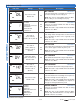
Error Messages (1 of 3) Error Message Description ADJUST ERROR The control failed to read the Adjust menu settings, and reloaded the factory default settings. Operation stops until you check the Adjust menu settings. Note: To clear the error, the access level must be set to Advanced and the settings in the Adjust menu must be checked. MISCELLANEOUS ERROR The control failed to read the Miscellaneous menu settings, and reloaded the factory default settings.
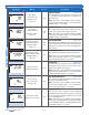
Error Messages (2 of 3) Error Message Description MIXING EXPANSION MODULE CONFLICT A Mixing Expansion Module is connected to the Boiler bus. The Mixing Expansion Module must be removed from the Boiler bus or the bus must be set to Mix 2 via the tN4 Boiler / Mix2 DIP switch. The error message self clears once the error condition is corrected. MIX 1 SENSOR SHORT CIRCUIT Due to a short circuit, the control failed to read the Mix 1 supply sensor.
Error Messages (3 of 3) Error Message Description BOILER BUS AND RETURN SENSOR CONFLICT There is a DIP switch settings conflict. The Boiler DIP switch is set to Ret and the tN4 bus DIP switch is set to Boiler. Once the Boiler DIP switch is set to Sup or the tN4 bus DIP switch is set to Mix 2, the error message clears. tekmar STAGER SETTING CONFLICT There is a DIP switch settings conflict. The tekmar Stager DIP switch is set to On and the Boiler Sensor DIP switch is set to Ret.
Limited Warranty and Product Return Procedure Limited Warranty The liability of tekmar under this warranty is limited. The Purchaser, by taking receipt of any tekmar product (“Product”), acknowledges the terms of the Limited Warranty in effect at the time of such Product sale and acknowledges that it has read and understands same.