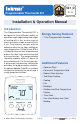
521_ D 01/14 Programmable Thermostat 521 Zoning Replaces: New Installation & Operation Manual Introduction The Programmable Thermostat 521 is designed for three different modes of operation: single stage heating, two stages of heating with a fan, or one stage of heating and one stage of cooling with a fan. Two auxiliary sensors may be added to measure the floor, outdoor or room temperature.
Table of Contents Getting Started ...............................2 Important Safety Information ...............3 Installation ...........................................4 Preparation .....................................4 Removing The Thermostat Base ....4 Mounting The Thermostat...............5 Slab Sensor 079 Installation ...........6 Slab Sensor 079 Wiring .................7 Slab Sensor 079 Testing .................8 Temperature vs. Resistance Table... 8 Thermostat Wiring .....................
Important Safety Information It is your responsibility to ensure that this control is safely installed according to all applicable codes and standards. tekmar is not responsible for damages resulting from improper installation and/or maintenance. To avoid serious personal injury and damage to the equipment: • Read Manual and all product labels BEFORE using the equipment. Do not use unless you know the safe and proper operation of this equipment. • Keep this Manual available for easy access by all users.
Installation Preparation Tools Required ---------------------------------------------------------------------------------------• tekmar or jeweller screwdriver • Wire Stripper • Phillips head screwdriver Materials Required ---------------------------------------------------------------------------------• 18 AWG LVT Solid Wire (Low Voltage Connections) Installation Location ------------------------------------------------------------------------------Choose the placement of the thermostats early in the const
Mounting The Thermostat Stud Adapter Plate 012 Thermostat Front Thermostat Base 3 1/4" (83 mm) Gang Box If a single gang box is used: • Adapter Plate 012 is required (sold separately). • Feed the wiring through the hole in the adaptor plate and the thermostat base. • Fasten the adaptor plate to the gang box. • Fasten the base of the thermostat to the adaptor plate. • Terminate wiring to the wiring strip. • Push the thermostat front onto the thermostat base.
Slab Sensor 079 Installation New Installations ----------------------------------------------------------------------------------Thin-Set or Thin-Pour Applications If the floor covering is to be installed over either a thin-set or thin-pour material of sufficient depth, the 079 slab sensor can be placed directly into either the thin-set material or the thin-pour material and covered over.
Retrofit Installations ----------------------------------------------------------------------------Tile Floor Coverings If a Slab Sensor 079 is to be installed into an existing tile floor with sufficiently large grout lines, the sensor and wire can be installed in one of the grout lines between the tiles. Select a low traffic area of the floor that is mid way between the heating elements for the sensor location.
Slab Sensor 079 Testing A good quality test meter capable of measuring up to 5,000 kΩ (1 kΩ = 1000Ω) is required to measure the sensor resistance. In addition to this, the actual temperature must be measured with either a good quality digital thermometer, or if a thermometer is not available, a second sensor can be placed alongside the one to be tested and the readings compared. First measure the room temperature using the thermometer. Disconnect the S1 or S2 and Com wires from the thermostat.
Temperature vs.
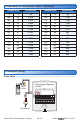
Thermostat Wiring Relay 003 ----------------------------------------------------------------------------------------------------- T T Field Jumper Required: R to Rh 2 1 8 7 3 4 5 6 Relay 003 No Power Boiler Pump L N C RC R Rh W1 Y/W2 Rc G G Com S1 S2 Transformer Wiring Center 315 or 316 --------------------------------------------------------------------Field Jumper Required: R to Rh No Power C tN4 R C R Rh W1 Y/W2 Rc G G Com S1 S2 W Wiring Center Switching Relay -------------------
Thermostat Wiring Air Conditioner --------------------------------------------------------------------------------------Field Jumper Required: Rc to G RY G C R Rh W1 Y/W2 Rc No Power G Com S1 S2 G Air Conditioner Furnace (second stage heat) --------------------------------------------------------------Field Jumper Required: Rc to G RWG C R Rh W1 Y/W2 Rc G No Power G Com S1 S2 Furnace Furnace and Air Conditioner ------------------------------------------------------------- Field Jumper Required:
Sensors---------------------------------------------------------------------------------------------------------Indoor Outdoor Slab Sensor Sensor Sensor 076, 077, 084 079 070 Or Or No Power C R Rh W1 Y/W2 Rc G G Com S1 S2 Or Indoor Slab Sensor Sensor 076, 077, 084 079 Testing the Thermostat Wiring Testing the Power -----------------------------------------------------------------------------------If the thermostat display turns on, this indicates that power is applied correctly.
Testing the Cooling Output Wiring -----------------------------------------------Cooling is only available when the switch setting is set to H/C/F. 1. Press the Mode button and set to Cool. 2. Press the button and set the cooling temperature below the current room temperature setting. 3. When the “Cool On” symbol appears on the display, use an electrical meter to check for voltage on the Y and C wires on the cooling equipment. The meter should read 10 to 30 V (ac) or (dc).
User Interface Home Screen SuMoTuWeThFrSa F P F MIN MAX MODE Heat Cool Off Floor Room Floor Heat On Cool On Mode Button Change operation from Heat, Cool and Off. Hold Button Permanently overrides the schedule. Press hold to cancel. Symbols Description HEAT ON Heat is turned on. SUN Schedule operating at the occupied temperature. COOL ON Cooling is turned on. MOON Schedule operating at the unoccupied temperature. FAN The fan is turned on. WARNING SYMBOL Indicates an error is present.
Programmable Settings Navigation 1. Press and hold down both the Menus. 2. While in the Programming Menus, the MODE button changes function to become the MENU button. and buttons together to enter the Programming 3. While in the Programming Menus, the HOLD button changes function to become the PRGM (program) button. PRGM MENU Press the MENU button to change from one menu to the next. Press the PRGM button to enter the menu. PRGM MENU PRGM MENU MENU PRGM MENU PRGM MENU PRGM 4.
Fan Menu Setting Display FAN Select if the fan should operate continuously (On) or only together with the heating or cooling equipment (Auto). Access Level: Installer, User Range: Auto or On Conditions: Only available when FAN MODE is not set to OFF and a room temperature sensor is available. Default: Auto Set Temp Menu Setting Display SET HEAT ROOM Set the room heating temperature for the event. Access Level: Installer, User Conditions: Room Sensor On or Sensor 1 or 2 is set to Room.
Set Temp Menu Setting Display SET FLOOR Set the floor heating temperature for the event. Access Level: Installer, User Conditions: Sensor 1 or 2 is set to Floor and Schedule is set to On. SET FLOOR MAXIMUM Set the maximum floor heating temperature. Range: OFF, 40 to 122°F (OFF, 4.5 to 50.0°C) Defaults Air & floor sensors: 65°F (18.5°C) Floor sensor only: OFF MAX Access Level: Installer Range: 40 to 122°F, OFF (4.5 to 50.0°C, OFF) Conditions: Sensor 1 or 2 is set to Floor. Default: 85°F (29.
Schedule Menu (1 of 2) The schedule menu can operate on a 24 hour or 7 day repeating schedule. When a 24 hour schedule is selected, “SuMoTuWeThFrSa” is shown on the top of the screen to show that the event time applies to all days of the week. When a 7 day schedule is selected, each individual day of the week is shown with the event time. Setting EVENT 1 The first programmable schedule time period of the day. The temperature settings are used during this time period.
Schedule Menu (2 of 2) Setting Display SCHEDULE Select if the thermostat should change the temperature automatically using a programmable schedule. Access Level: Installer, User Range: OFF or On Conditions: Always available Default: OFF EVENT PER DAY Select either two or four scheduled events per day. Access Level: Installer, User Range: 2 or 4 Conditions: Schedule setting is set to On. Default: 2 24 HOUR / 7 DAY Select either a 24 hour or a 7 day repeatable schedule.
Setup Menu (1 of 2) Setting Display ACCESS Selects the access level of the thermostat, which determines which menus and items are available. Access Level: Installer, User Range: Installer or User Conditions: Only available when switch setting 1 is Default: Installer set to Unlocked. UNITS Select the temperature units. Access Level: Installer, User Conditions: Always available. LIGHT Select when the display back light should operate. Auto operates the back light for 30 seconds after a keystroke.
Setup Menu (2 of 2) Setting Display W2 RELAY Select if a second stage heat is available. Access Level: Installer Range: OFF or On Conditions: Available when switch setting 2 is set Default: OFF to 1H or 2H. W2 DELAY Select the time delay that the second stage must wait before turning on. Access Level: Installer Range: 1 to 180 minutes Conditions: Available when switch setting 2 is set to Default: 20 minutes 1H or 2H and W2 Relay is set to On.
Sequence of Operation Mode Button Operation Pressing the Mode button selects the operation of the thermostat to be either Heating, Cooling, or Off. The thermostat must be configured for heat/cool/fan operation in order for the cooling operation to be available. Heating Operation Heating is available when the Mode is set to Heat. To change the heat temperature setting, push the or button to select a preferred temperature setting for the current schedule time period.
This operation is also recommended for rooms with hardwood floors. Setting floor minimum and maximum temperatures is a way of enhancing the comfort of the living space while protecting floor coverings. 90°F (32°C) Feels hot to the touch Suggested maximum for all floor types other than wood. 80 to 85°F (26 to 30°C) Feels warm to the touch Bathrooms and kitchens. Suggested maximum for wood floors. 70°F (21°C) Feels cool to the touch Rooms with large windows preventing under heating in the evening.
Fan Operation A fan is available when the thermostat operates a forced air heating or cooling system. The fan can be set to On to allow air circulation through the building. This is useful if the air in the room is stale or if circulating cool air from a basement throughout a home can reduce the temperature in the upper floor without operating the cooling equipment. Time Clock The thermostat includes a time clock that is automatically visible in the Home menu when a programmable schedule is used.
Optimum Start When a programmable schedule is selected, there is a time delay for the room to warm up from the temperature to the temperature. The thermostat has the option to use Optimum Start to predict the heat up rate of the room. When Optimum Start is set to On, the heating is started in advance to allow the room to reach the Set Room temperature at the time set in the programmable schedule.
Troubleshooting Error Messages Error Message Description SETUP MENU SAVE ERROR The thermostat failed to read the Programmable Settings from memory and has reloaded the factory default settings. The thermostat stops normal operation until the access level is changed to Installer and all Programmable Settings are checked. The thermostat continues to provide freeze protection. Room Room ROOM SENSOR OPEN CIRCUIT ERROR The built-in air temperature sensor has an open circuit fault.
Frequently Asked Questions Symptom Look for... Corrective Action Display powering on and off. Measure voltage at wiring terminals R and C. The power supply transformer may have limited VA capacity. A transformer with a larger VA rating is recommended. Mode Off or Cool Thermostat must be in Mode Heat in order to provide heating. Floor Max The floor has reached the maximum operating temperature. Room is too hot due to floor heating being on Floor Min Lower the Set Floor temperature setting.
Limited Warranty and Product Return Procedure Limited Warranty The liability of tekmar under this warranty is limited. The Purchaser, by taking receipt of any tekmar product (“Product”), acknowledges the terms of the Limited Warranty in effect at the time of such Product sale and acknowledges that it has read and understands same.