
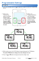
Installation Guide


© 2014 521_D - 01/14
12 of 28
A Watts Water Technologies Company
Testing the Thermostat Wiring
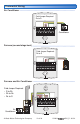
Testing the Power
--------------------------------------------------
--------------------------------------------------
If the thermostat display turns on, this indicates that power is applied correctly. In the
event that the display is permanently off:
1. Remove the thermostat front.
2. Use an electrical meter to measure voltage between the R and C wiring terminals.
For AC power supplies the voltage should measure between 10 to 30 V (ac). For
DC power supplies the voltage should measure between 10 to 30 V (dc).
3. If the voltage on the R and C wire terminations is continuous and the thermostat
display is not on, the thermostat may have a fault. Contact your tekmar sales
representative for assistance.
If the thermostat display initially powers on but later shuts off intermittently, there may
be a short circuit from the W1, W2, Y or G wire to the power common or ground, or
the power supply is too small to power the load.
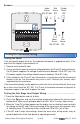
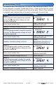
Testing the First Stage Heat Output Wiring
---------------------------
---------------------------
1. Press the Mode button and set to Heat.
2. Press the
button and set the heating temperature above the current room
temperature. Make sure the display does not flash “Max” if using a floor sensor.
3. When the “Heat On” symbol appears on the display, use an electrical meter to check
for voltage on the W1 and C wires connected to the zone valve, wiring center, relay
or switching relay. The electrical meter should read 10 to 30 V (ac) or (dc).
4. If the W1 and C wires have voltage, check the zone valve, wiring center, relay or
pump to determine if the heat device is operating correctly.
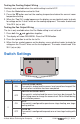
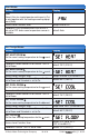
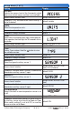
Sensors
------------------------------------------------------------
------------------------------------------------------------
C R
Y/W2
Rc GGRh W1 S1 S2Com
No Power
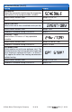
Indoor
Sensor
076, 077, 084
Outdoor
Sensor
070
Slab
Sensor
079
Indoor
Sensor
076, 077, 084
Slab
Sensor
079
Or
Or Or