TEKTELIC COMMUNICATIONS INC. Document type: User Guide Document number: T0006326_UG Document version: 0.4 Document Status: Approved Product name: DISH Macro Gateway Product codes: See Table 1 TEKTELIC Communications Inc. 7657 10th Street NE Calgary, AB, Canada T2E 8X2 Phone: (403) 338-6900 © 2019 TEKTELIC Communications Inc., All rights reserved. All products, names and services are trademarks and registered trademarks of their respective companies.
Revision History Version Date Status Editor Comments 0.2 0.3 Jan. 11, 2018 Feb, 01, 2018 Draft Draft S. Morrison S. Morrison 0.31 Feb. 13, 2018 Draft T. Danshin 0.32 Feb. 13, 2018 Draft T. Danshin 0.33 0.34 0.4 0.5 Feb 14, 2018 Feb 14, 2018 May 27, 2019 June 12, 2019 Approved Approved Approved Approved T. Danshin T. Danshin T. Danshin Z.
Table of Contents 1 2 3 4 Product Description ................................................................................................................. 4 1.1 Overview .......................................................................................................................... 4 1.2 Physical Interfaces ............................................................................................................ 5 1.3 Specifications..................................................
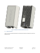
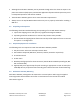
1 Product Description 1.1 Overview The Dish Macro Gateway is an outdoor hardened LoRaWAN IoT gateway that supports the full range of LoRaWAN uplink channels while supporting the DISH custom downlink channels in the 722-728MHz band. The Gateway supports one external LoRa antenna, an internal GPS antenna, two power options including direct DC input power or Power over Ethernet (PoE), and two backhaul options including copper Ethernet or 3G/4G wireless.
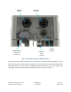
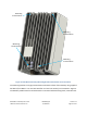
Figure 1: Dish Macro Gateway Common Dimensions 1.2 Physical Interfaces Figure 2 illustrates the bulkhead layout for the Dish Macro Gateway. All models share the same bulkhead layout. DISH Macro Gateway User Guide TEKTELIC Communications Inc. T0006326_UG Confidential Version 0.
Copper Ethernet 3G/4G Modem SIM card access port DC Power 2 pin CPC Protective Earth Ground LoRa RF Antenna Figure 2: Dish Macro Gateway Bulkhead Layout All Kona Gateway module interconnect is located on the bottom facing bulkhead. The RF connectors are water proof while un-mated but all other connectors must be terminated with mating connectors or covered with the supplied protective cap when not in use in order to be water tight. Connector types and their mating connectors are listed in Table 2.
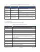
Table 2: Dish Macro Gateway Interface Connector Types Interface Connector Type Mating Connector LoRa Antenna Ports N-Type female Industry standard N-Type male 3G/4G Modem SIM card SIM card Industry standard, located behind SIM card access port cover Copper Ethernet Port Threaded, circular, RJ-45 Shenzhen Chogori Technology Co., Ltd. approved mating connector (p/n 33000111-02 or equivalent) Direct DC Power Input Port Threaded, circular, 2 contact DC power Shenzhen Chogori Technology Co., Ltd.
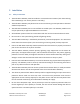
2 Installation 2.1 Safety Precautions • The Dish Macro Gateway must be installed in a restricted access location (such that touching of the Gateway by non-service persons is not likely). • The Dish Macro Gateway may become hot to the touch during normal operation at elevated ambient temperatures. • The Dish Macro Gateway has no internal field serviceable parts. The Gateway module must only be opened by an approved TEKTELIC service center.
• Although the Dish Macro Gateway can be powered through either the direct DC input or the power over Ethernet (PoE) input, simultaneous application of power to both inputs may result in unexpected operation and shall be avoided. • The Dish Macro Gateway power source must meet SELV requirements. • Always ensure the 3G/4G Modem SIM card access port is properly sealed after installing a SIM card. 2.
Mounting screw location Mounting screw location Mounting screw location Mounting screw location Figure 3: Dish Macro Gateway Mounting Bracket Attachment Screw Locations The mounting bracket is a single part that bolts to the back surface of the Gateway using supplied hardware (four M6x1.0 - 14 mm bolts with flat and star lock washers) as illustrated in Figure 4. The Gateway module must be oriented with the connector bulkhead facing down, towards earth.
Mounting Bracket Figure 4: Dish Macro Gateway Module with Mounting Bracket Ensure that the structure to which the Gateway is being mounted is secure and able to support a dead load of at least 136 kg (300 lbs). The area below must be free of any obstructions to cable ingress. The Dish Macro Gateway wall mounting procedure is as follows: 1. Bolt the wall mounting bracket to the Gateway module using the supplied bolts and washers. 2. Install 2 site supplied M8 bolts into the wall at 139.7 mm (5.
1. Bolt the wall mounting bracket to the Gateway module using the supplied bolts and washers. 2. While temporarily supporting the Gateway with bracket, install the two site supplied pipe clamps, one through each of the upper and lower slotted clamp mounting points. 2.5 Ground Cable Installation The Dish Macro Gateway is considered Permanently Connected Equipment and requires a permanently connected Protective Earth Ground (PEG) conductor. The Protective Earth Ground connection is made through a 1/4 x 0.
Chassis Ground Connection Figure 5: Chassis Ground Connection 2.6 Direct DC Power Cable Installation The Dish Macro Gateway direct DC feed terminates at a dedicated two pin circular plastic connector (CPC) on the bulkhead. The direct DC power input is isolated from chassis (earth) with the exception of the primary surge suppressors. One lead of the DC power feed is normally earth referenced external to the Dish Macro Gateway (usually at the power source by convention).
Black DC Negative Keyed DC Power Connector (CPC) White DC Positive DC Positive DC Negative Figure 6: Direct DC Power CPC Connector Connection Polarity 2.7 RF Cable Installation The Dish Macro Gateway installation requires connection to a LoRa RF antenna. The RF cable attaches to the N-Type connector located on the bulkhead of the Gateway. Torque the connector to 1.7 to 2.3 Nm (15 to 20 in·lbs). The N-Type connector interface to a cable is not water proof and must be taped to be used outdoors.
3 Commissioning and Monitoring 3.1 Required Equipment The following equipment is required for commissioning and monitoring the Dish Macro Gateway. 1. A laptop running Windows XP/Vista/7. 2. A Cat5 or better Ethernet cable. 3.2 Procedure Once the DC power and GPS and LoRa RF antenna connections are in place the Dish Macro Gateway may be commissioned. 1. Connect an Ethernet cable between the Host PC and the bulkhead copper Ethernet connector (RJ45).
4 Radio Compliance Statements Federal Communications Commission This device complies with Part 15 of the FCC Rules. Operation is subject to the following two conditions: 1. 2. This device may not cause harmful interference, and This device must accept any interference received, including interference that may cause undesired operation. Changes or modifications not expressly approved by the party responsible for compliance could void the user’s authority to operate the equipment.