TEKTELIC COMMUNICATIONS INC. Document type: User Guide Document number: T0007871_UG Document version: 1.5 Document Status: Approved Product name: Kona Micro Gateway Product codes: See Table 1 TEKTELIC Communications Inc. 7657 10th Street NE Calgary, AB, Canada T2E 8X2 Phone: (403) 338-6900 © 2021 TEKTELIC Communications Inc., All rights reserved. All products, names and services are trademarks and registered trademarks of their respective companies.
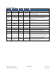
Revision History Version Date Status Editor Comments 0.1 Feb 7, 2018 Obsolete H. Agus 0.11 Feb. 14, 2018 Obsolete T. Danshin 0.20 Feb. 15, 2018 Obsolete S. Morrison 0.12 Feb. 23, 2018 Obsolete T. Danshin 0.13 Feb. 23, 2018 Obsolete T. Danshin First release Reduced content to that required specifically for regulatory filings Numerous updates from review. Updated MPE information in compliance section.
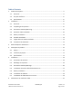
Table of Contents 1. 2. Product Description ................................................................................................................. 4 1.1. Overview .......................................................................................................................... 4 1.2. Physical Interfaces ............................................................................................................ 6 1.3. Specifications...................................................
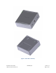
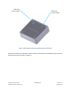
1. Product Description 1.1. Overview The Kona Micro Gateway is a LoRaWAN IoT gateway that supports the full range of LoRa WAN channels. The Gateway supports one external LoRa antenna, copper Ethernet backhaul, and optional 3G/4G wireless backhaul. All Gateway models are powering from an AC-DC power adapter and may optionally have an internal backup battery provisioned. Table 1 presents the currently available Kona Micro Gateway models. Any model may have a backup battery provisioned.
Figure 1: Kona Micro Gateway Kona Micro User Guide TEKTELIC Communications Inc. T0005281_UG Version 1.
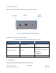
1.2. Physical Interfaces Figure 2 illustrates the connector layout for the Kona Micro Gateway. Ethernet DC Power LoRa RF Antenna Figure 2: Kona Micro Gateway Bulkhead Layout The Gateway connectors are listed in Table 2. Table 2: Kona Micro Gateway Interface Connector Types Interface Connector Type Mating Connector LoRa Antenna Ports Reverse SMA female Industry standard Reverse SMA male DC Barrel plug DC Power Input Port Barrel Jack Ethernet Port RJ-45 2.1 mm (inner), 5.
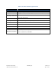
Table 3: Kona Micro Gateway Specifications Attribute Specification Dimensions 120 (L) x 118 (W) x 41.5 (H) mm Weight 336 g (0.74 lbs) with battery, 245 g (0.54 lbs) without battery Operating Temperature 0°C to 40°C without battery 0°C to 38°C with battery Relative Humidity 5 to 95 %RH Operating Altitude -60 m to 4,000 m (-197 ft to 13,123 ft) Power Input 12 VDC +/-10% Power Consumption 12 W DC maximum Battery 7.
2. Installation 2.1. Overview • The Kona Micro Gateway is intended for indoor use only. • The Kona Micro Gateway has no internal field serviceable parts other than the battery. Other than installing or replacing the battery, the Gateway module must only be opened by an approved TEKTELIC service center. • All installation practices must be in accordance with the local and national electrical codes. • Ensure that the Kona Micro Gateway is located to eliminate any physical hazard to people or property.
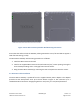
Mounting screw location Mounting screw location Figure 3: Kona Micro Gateway Mounting Screw Locations While wall mounted, the Gateway module must be oriented with the TEKTELIC logo horizontal, parallel to the earth as shown in Figure 4. Kona Micro User Guide TEKTELIC Communications Inc. T0005281_UG Version 1.
Figure 4: Kona Micro Gateway Module Wall Mounting Orientation Ensure that the wall on which the Gateway is being mounted is secure, flat and able to support a load of at least 0.5 kg (1.1 lbs). The Kona Micro Gateway wall mounting procedure is as follows: 1. Install the M3 screws into the wall. 2. Install 2 site supplied M3 screws into the wall at 60 mm (2.4”) center spacing, leaving the screw heads protruding with a 3 mm gap from the wall surface. 3.
Figure 5: DC Power Connection Polarity 2.5. Battery Installation Use only a battery provided by Tektelic Communications Inc. Dispose of old batteries in accordance with regulatory requirements. Remove the battery cover by removing the two Torxdrive battery cover securement screws. Connect the 3-pin battery connector to the connector at the bottom of the battery compartment and then insert the battery into the battery compartment as illustrated in Figure 6.
Figure 6: Battery Installation 2.6. RF Cable Installation The Kona Micro Gateway installation requires connection to a LoRa RF antenna. The antenna attaches to the reverse SMA connector located on the side of the Gateway. Torque the connector to 5 in·lbs. The Kona Micro is not protected from lighting surge as it is intended for Indoor use. Do not connect to an outdoor antenna. Note that the 3G/4G modem antenna is internal to the Kona Micro Gateway. 2.7.
Kona Micro User Guide TEKTELIC Communications Inc. T0005281_UG Version 1.
3. Radio Compliance Statements Federal Communications Commission This device complies with Part 15 of the FCC Rules. Operation is subject to the following two conditions: 1. 2. This device may not cause harmful interference, and This device must accept any interference received, including interference that may cause undesired operation. Changes or modifications not expressly approved by the party responsible for compliance could void the user’s authority to operate the equipment.
4. Description du produit 4.1. Aperçu Le Kona micro Gateway est une passerelle intérieure LoRaWAN ITO qui prend en charge la gamme complète des canaux de Lora WAN. La passerelle prend en charge une antenne Lora externe, un câble Ethernet en cuivre et une connexion sans fil 3G/4G en option. Tous les modèles Gateway sont alimentés à partir d'un adaptateur secteur AC-DC et peuvent éventuellement avoir une batterie de secours interne provisionnée.
La figure 7 illustre le facteur de forme externe Kona Micro Gateway avec la vue de face en haut et la vue arrière en bas. Tous les modèles partagent le même facteur de forme mécanique. Figure 7: Passerelle intérieure Kona Micro Kona Micro User Guide TEKTELIC Communications Inc. T0005281_UG Version 1.
4.2. Interfaces physiques Figure 8 illustre la disposition de la cloison de la Kona Micro Gateway. Ethernet DC Power LoRa RF Antenna Figure 8: Kona Micro Gateway Mise en page de cloison Les connecteurs de la passerelle intérieure sont répertoriés dans Table 5.
Table 6: Kona Micro Gateway Spécifications Attribute Spécifications Dimensions 120 (L) x 118 (W) x 41.5 (H) mm Poids 336 g (0.74 lbs) avec batterie, 245 g (0.54 lbs) sans batterie Température de fonctionnement 0°C to 40°C sans batterie Humidité relative 5 to 95 %RH Altitude de fonctionnement -60 m to 4,000 m (-197 ft to 13,123 ft) Entrée de puissance 12 VDC +/-10% Consommation d'énergie 12 W maximum Batterie 7.
5. Installation 5.1. Précautions de sécurité • La passerelle intérieure Kona Micro est conçue pour une utilisation en intérieur uniquement. • La passerelle interne Kona Micro ne comporte aucune pièce interne réparable sur place autre que la batterie. En dehors de l'installation ou du remplacement de la batterie, le module passerelle ne doit être ouvert que par un centre de service agréé TEKTELIC. • Toutes les pratiques d'installation doivent être conformes aux codes électriques locaux et nationaux.
5.3. Kona Micro Gateway Montage Kona Micro Gateway peut être placé sur une surface plane ou peut être fixé à un mur avec des vis M3 à l'arrière du module illustré à la Figure 9. Emplacement de la vis de montage Emplacement de la vis de montage Figure 9: Emplacements des vis de montage Kona Micro Gateway Lorsqu'il est fixé au mur, le module Gateway doit être orienté avec le logo TEKTELIC horizontalement, parallèlement à la terre comme indiqué dans figure 9.
Figure 10: Kona Micro Gateway Orientation de montage mural Assurez-vous que le mur sur lequel la passerelle est montée est bien fixé, plat et capable de supporter une charge d'au moins 0,5 kg (1,1 lb). La procédure de montage mural Kona Micro Gateway est la suivante: 1. Installez les vis M3 dans le mur 2. Installez 2 vis M3 fournies dans le mur à un espacement central de 60 mm (2,4 "), en laissant les têtes de vis dépasser d'un espace de 3 mm de la surface de la paroi. 3.
Figure 11: Polarité directe du connecteur d'alimentation CC 5.5. Battery Installation Utilisez uniquement une batterie fournie par Tektelic Communications Inc. Éliminez les batteries usagées conformément aux exigences réglementaires. Retirez le couvercle de la batterie en retirant les deux vis de fixation du couvercle de la batterie du lecteur Torx.
Figure 12: Battery Installation Kona Micro User Guide TEKTELIC Communications Inc. T0005281_UG Version 1.
5.6. Installation du câble RF Le Kona micro Gateway installation nécessite une connexion à une antenne Lora RF. L'antenne s'attache au connecteur SMA inversé situé sur le côté de la passerelle. Serrez le connecteur à 5 in · lbs. Le Kona micro n'est pas protégé contre les surtensions d'éclairage car il est destiné à une utilisation à l'intérieur. Ne pas raccorder à une antenne extérieure. Notez que l'antenne du modem 3G / 4G est interne à la Kona Micro Gateway. 5.7.
6. Déclarations de conformité radio Industrie Canada Cet appareil est conforme aux normes RSS exemptes de licence d'Industrie Canada. Le fonctionnement est soumis aux deux conditions suivantes: 1. Cet appareil ne peut pas causer d'interférences, et 2. Cet appareil doit accepter toute interférence, y compris les interférences susceptibles de provoquer un fonctionnement indésirable de l'appareil.