Model 6519 ® TUBING BENDER 1/4 in. 5/16 in. 3/8 in. O.D. OPERATOR’S MANUAL STORE THIS MANUAL IN A SAFE PLACE FOR FUTURE REFERENCE !? NEED HELP? Save time, contact us first. 888-648-8665 support@tektontools.
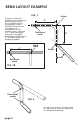
BEND LAYOUT EXAMPLE FIG. 1 To measure tubing for bending, use the center line of the tubing as shown. When establishing first measurement, make a REFERENCE mark for the starting point of measurement. In the example shown, a distance of 5" is desired between reference mark and 90˚ bend. Make a BEND mark at 5". Proceed to page 2 for bending procedure. 5" Vertex 5" Reference mark 5" Bend mark Vertex 45˚ Reference mark FIG. 1B Directional marks FIG.
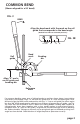
COMMON BEND (Shown aligned for a 90˚ bend) FIG. 3 BEND Align the bend mark with the mark on the roll guide that corresponds to the bend angle. (Dashed lines indicate estimated positions.) 0 15˚ 30˚ 45˚ Bend mark Roll guide 75˚ 90˚ Bending die 4 5 L 9 0 5 18 0 0 0 R 60˚ FIG. 3B 13 0 R L Align “0” marks on roll guide and bending die Reference mark For common bending, open arms of tubing bender to position shown above. Insert tubing into correct size channel.
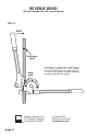
REVERSE BEND (Shown aligned for a 90˚ reverse bend) FIG. 4 BEND Reference mark Sometimes it is necessary to bend tubing in a reverse position. For a 90˚ reverse bend, the BEND mark must align with the "R" line on roll guide. Complete bending procedure described on page 3. Bend mark 18 0 4 R 0 5 0 0 13 5 L 9 0 Michigan Industrial Tools 3707 Roger B. Chaffee Dr. Grand Rapids, MI 49548 page 4 © Copyright 2013 Michigan Industrial Tools TEKTONTOOLS.