
User's Manual

Functional Overview
2-12 GB1400 User Manual
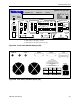
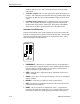
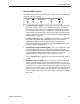
Generator Rear Panel
The rear-panel of the Generator contains the auxiliary signals, remote control,
and AC-power inputs shown below. See the appendix for instruction on how to
set up the RS-232 and GPIB ports, and general information on using external
controllers with the Generator.
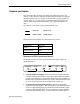
• PHASE A: An SMA connector provides signal output for DATA Phase A.
This phase-shifted data pattern provides signals suitable for MUX/DEMUX
testing. Phase A/B outputs are half rate data patterns (alternating bits).
• PHASE B: : An SMA connector provides signal outputs for DATA Phase
B. This phase-shifted data pattern provides signals suitable for
MUX/DEMUX testing.
• CLOCK/2: : An SMA connector provides signal outputs for CLOCK/2.
• ERROR INJECT: An ECL signal applied to this input may be used to
control error injection when the Generator is in the external (EXT ERR)
injection mode. One error will occur for each rising edge of this signal.
• DATA INHIBIT: An ECL signal applied to this input may be used to
asynchronously gate off the data outputs of the Generator.
• RS-232C [input/output]: A two-way serial port that may be connected to
an external controller or serial printer.
• GPIB [input/output]: An IEEE-488 standard I/O port that may be
connected to a GPIB compatible controller. This port is not compatible with
stand-alone GPIB printers.
• AC LINE [power input]: This is the AC power input connector for the
Generator.
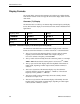
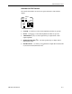
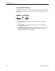
Changing the Line Fuse
1. Disconnect the AC line cord.
2. Slide the fuse cover upwards and remove the fuse.
3. Install the correct line fuse into the holder.
115 VAC 5A, Slo-Blo
230 VAC 5A, Slo-Blo
4. Close the fuse cover.
5. Plug in the line cord.
Allow at least two inches of clearance for the rear panel fan opening and at least
one inch of clearance for the top of the unit. This assures proper cooling of the
unit. Do not operate the Generator on its rear side.
PHASE A PHASE B CLOCK/2 ERROR INJECT DATA INHIBIT