User Manual 80E01, 80E02, 80E03, 80E04 & 80E06 Electrical Sampling Modules 071-0434-05 This document applies to firmware version 1.00 and above. www.tektronix.
Copyright © Tektronix. All rights reserved. Licensed software products are owned by Tektronix or its subsidiaries or suppliers, and are protected by national copyright laws and international treaty provisions. Tektronix products are covered by U.S. and foreign patents, issued and pending. Information in this publication supercedes that in all previously published material. Specifications and price change privileges reserved. TEKTRONIX and TEK are registered trademarks of Tektronix, Inc.
Warranty 2 Tektronix warrants that this product will be free from defects in materials and workmanship for a period of one (1) year from the date of shipment. If any such product proves defective during this warranty period, Tektronix, at its option, either will repair the defective product without charge for parts and labor, or will provide a replacement in exchange for the defective product.
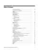
Table of Contents General Safety Summary . . . . . . . . . . . . . . . . . . . . . . . . . . . . . . . . . . . Environmental Considerations . . . . . . . . . . . . . . . . . . . . . . . . . . . . . . . Preface . . . . . . . . . . . . . . . . . . . . . . . . . . . . . . . . . . . . . . . . . . . . . . . . . . . iii v vii Manual Structure . . . . . . . . . . . . . . . . . . . . . . . . . . . . . . . . . . . . . . . . . . . . . . . . Related Documentation . . . . . . . . . . . . . . . . . . . . . . . . . . .
Table of Contents List of Figures Figure 1: Sampling module block diagram . . . . . . . . . . . . . . . . . . . . . Figure 2: Sampling module, 80E04 shown . . . . . . . . . . . . . . . . . . . . . Figure 3: Sampling module compartments . . . . . . . . . . . . . . . . . . . . . Figure 4: Installing a sampling module . . . . . . . . . . . . . . . . . . . . . . . . Figure 5: Sampling module, 80E04 shown . . . . . . . . . . . . . . . . . . . . . Figure 6: Vertical Setup dialog box . . . . . . . . . . . . . . .
General Safety Summary Review the following safety precautions to avoid injury and prevent damage to this product or any products connected to it. To avoid potential hazards, use this product only as specified. Only qualified personnel should perform service procedures. While using this product, you may need to access other parts of the system. Read the General Safety Summary in other system manuals for warnings and cautions related to operating the system.
General Safety Summary Symbols and Terms Terms in this Manual. These terms may appear in this manual: WARNING. Warning statements identify conditions or practices that could result in injury or loss of life. CAUTION. Caution statements identify conditions or practices that could result in damage to this product or other property. Terms on the Product. These terms may appear on the product: DANGER indicates an injury hazard immediately accessible as you read the marking.
Environmental Considerations This section provides information about the environmental impact of the product. Product End-of-Life Handling Observe the following guidelines when recycling an instrument or component: Equipment Recycling. Production of this equipment required the extraction and use of natural resources. The equipment may contain substances that could be harmful to the environment or human health if improperly handled at the product’s end of life.
Environmental Considerations vi 80E00 Electrical Sampling Modules User Manual
Preface This is the user manual for the 80E01, 80E02, 80E03, 80E04, and 80E06 sampling modules. It covers the following information: H Description of the capabilities of the sampling modules and how to install them H Explanation of how to operate the sampling modules: how to control acquisition, processing, and input/output of information H List of the specifications of the sampling modules You may want to visit the Tektronix Website at http://www.tektronix.
Preface viii 80E00 Electrical Sampling Modules User Manual
Getting Started The Tektronix 80E01, 80E02, 80E03, 80E04, and 80E06 sampling modules are high-performance sampling modules that can be installed in the following main instruments: H DSA8200 Digital Serial Analyzer H CSA8000, CSA800B, and CSA8200 Communications Signal Analyzers H TDS8000, TDS8000B, and TDS8200 Digital Sampling Oscilloscopes Proper operation of the electrical sampling modules requires that the appropriate application software is installed on the main instrument.
Getting Started Product Description The sampling modules provide the features shown in Table 2. Table 2: Sampling module features Feature 80E01 80E02 80E03 80E04 80E06 2 2 2 1 7 ps, typical1 ≤28 ps ≤17.5 ps ≤17.5 ps ≤5.0 ps, typical1 50 GHz 12.5 GHz 20 GHz 20 GHz 70 GHz, typical ≤2.3 mVRMS ≤800 VRMS ≤1.2 mVRMS ≤1.2 mVRMS ≤2.
Getting Started 50 Ω Sampler To main instrument Strobe Generator Sampler Strobe drive From main instrument Note: the 80E01and 80E06 are single channel modules with a dedicated strobe drive and generator.
Getting Started Options and Accessories This section lists the standard and optional accessories available for the sampling modules.
Getting Started Table 4: Optional accessories (cont.) Item Part number Power divider 015-0565-xx SMA accessory kit 020-1693-xx Torque wrench, 8 mm (5/16 inch) open end n.a. 3.5 male to 3.5 female SMA 015-0552-xx Slip-on SMA connector 015-0553-xx 3.
Getting Started Installation The sampling modules fit into the front panel of the main instrument. Figure 3 shows the front panel of a DSA8200 and the locations of the sampling-module compartments.
Getting Started Know your signal source. If it is capable of delivering overvoltages, it is safer to not depend on the signal source settings for protection, but instead use an external attenuator that protects the input from the worst-case conditions. For example, for a 20 V maximum source connected to a 3 V maximum sampling module, use a 10X attenuator. Where possible, connect your cables to the signal source first, and to the sampling module second. CAUTION.
Getting Started Module Installation To install a sampling module, first turn off the instrument using the front-panel On/Standby switch. Then place the sampling module in a compartment and slowly push it in with firm pressure. Once the sampling module is seated, turn the hold-down screw on the sampling module to tighten the sampling module into place. See Figure 4. CAUTION.
Getting Started Compensation After installing a sampling module or after moving a sampling module from one compartment to another, you should run compensation from the Utilities menu to ensure the instrument meets it specifications. Also run a compensation (accessed from the Utilities menu) when doing the following: H Installing an 80E00 sampling-module extender between the instrument and an 80E00 sampling module, where none was used before.
Getting Started 10 80E00 Electrical Sampling Modules User Manual
Operating Basics This chapter makes you familiar with the operation of your sampling module. It describes the front-panel controls and connectors, interaction of the sampling module with your main instrument, programming the sampling module, and user adjustments. Usage Figure 5 shows the front panel of the sampling module and identifies the buttons, lights and connectors. CAUTION.
Operating Basics Front-Panel Controls Each sampling module contains two identical input channels (80E01 and 80E06 each have one channel). This section describes channel controls, connectors, and indicators.
Operating Basics TEKPROBE Connector TDR On Indicator H If you press the button and the channel is not currently acquiring (for any channel or math waveform), then the instrument activates (turns on) the channel. H If you press the button and the channel is currently active as a channel waveform, then the instrument selects the channel waveform. H If the channel waveform is already selected when you press the channel button, the instrument turns the channel off.
Operating Basics Figure 6: Vertical Setup dialog box Programmer Interface Commands The remote-programming commands for all sampling modules are documented in the online Programmer Guide. User Adjustments All sampling module setups, parameters, and adjustments are controlled by the main instrument. To save, recall, or change any module settings, use the instrument menus or front-panel controls or consult the online help accessed from the main instrument.
Operating Basics WARNING. To prevent injury, power down the instrument and disconnect it from line voltage before performing any cleaning. Clean the exterior surfaces of the module with a dry, lint-free cloth or a softbristle brush. If any dirt remains, use a damp cloth or swab dipped in a 75% isopropyl alcohol solution. Use a swab to clean narrow spaces around controls and connectors. Do not allow moisture inside the module. Do not use abrasive compounds on any part of the chassis, as they may damage it.
Operating Basics 16 80E00 Electrical Sampling Modules User Manual
Reference This chapter contains the following sections: H Taking TDR Measurements describes how to use the 80E04 sampling module to perform time-domain-reflectometry (TDR) measurements. H TDR Measurements Background contains information that describes the cause of reflections, measurement range, the velocity of propagation and measuring mismatches, measurement units, and considerations for making accurate measurements.
Reference Keys to Using Read the following topics; they provide details that can help you set up and take effective TDR measurements. TDR Step Generation. Both channels in the 80E04 TDR/sampling module have a selectable polarity step generator which gives both channels measurement capabilities. You can use the outputs of both generators to perform differential and common-mode TDR measurements. The step generator circuitry consists, fundamentally, of a polarity-selectable current source and a diode switch.
Reference propagation time from the acquisition point to the short in the device under test and back. See Figure 8. 250 mV Ei Er 0V Figure 8: Step generator with a shorted output Operation Into a 50 Ω Load. Initially, the diode switch is conducting --10 mA. Since the step-generator output is connected to a 50 Ω load, the resistance to ground at the acquisition point is 25 Ω (because of the internal 50 Ω impedance).
Reference When the diode switch opens (reverse-biased), apparent resistance to ground at the acquisition point (and at the channel connector) is 25 Ω because the internal termination resistance is 50 Ω in parallel with the connector impedance of 50 Ω. The voltage at the acquisition point rises to +250 mV. The transition propagates to the open in the DUT and is positively reflected back to the acquisition point, causing the voltage at the acquisition point to rise to +500 mV.
Reference Ei Ei Ei Open circuit termination, ZL = 1, Er = Ei 2Z 0 Line terminated in a series R-L Ei/3 Ei Ei Line terminated in ZL = 2Zo, Er = Ei/3 Line terminated in a shunt R-C Z0 Ei Line terminated in Characteristic Zo, ZL = Zo, Er = 0 Ei Z 0/2 —Ei/3 Line terminated in a shunt R-L Ei Line terminated in ZL = Zo/2, Er = —Ei/3 Ei —Ei Ei Short circuit termination, ZL = 0, Er = —Ei Line terminated in a series R-C Figure 11: TDR displays for typical loads 80E00 Electrical Sampling Modules Us
Reference To Take a TDR Measurement Overview This example demonstrates the TDR feature of the 80E04 sampling module. TDR is a method of examining and measuring a network or transmission line by sending a step into the network and monitoring the reflections. To take a TDR measurement Prerequisites 1. Control elements & resources Connect your wrist strap to the antistatic connector on the front of your instrument. See Caution on page 7. Connect wrist strap 2.
Reference Overview To take a TDR measurement (cont.) Set other TDR 7. parameters Adjust the VERTICAL SCALE (500 mρ/div in this example) and HORIZONTAL SCALE (2 ns/div in this example) to show a trace similar to that shown. Leave at least one division of baseline trace to the left of the first rise.
Reference Overview To take a TDR measurement (cont.) Control elements & resources Specifying hori- 11. Select the HORIZONTAL tab. zontal timebase Distance units 12. Select the Distance radio button. Use this control to button specify the type of units to use for the horizontal axis for all timebases. You can select from seconds, bits, or distance. The timebase scale and position controls adopt the units you select. 13.
Reference Overview To take a TDR measurement (cont.) Control elements & resources Take automatic 16. Use the Vertical buttons to select the TDR waveform to measurements be measured. 17. Select one of the measurement tool bars. 18. Click the measurement you want (such as mean) in the measurement tool bar. 19. Read the results in the measurements readout. 20. To take your measurement over a portion of the waveform, select the Region tab to display the gate controls.
Reference Overview Take cursor measurements To take a TDR measurement (cont.) Control elements & resources 23. Press the SETUP DIALOGS button and select the Cursor tab. 24. Select the Waveform cursor type. Click to access sources 25. From the pop-up list for each of Cursor 1 and Cursor 2, select your TDR source. Select source from pop-up list 26. Press the SELECT button to toggle selection between the two cursors. The active cursor is the solid cursor. 27.
Reference TDR Measurements Background TDR is based on a simple concept: Whenever energy transmitted through any medium encounters a change in impedance, some of the energy is reflected back toward the source. The amount of energy reflected is a function of the transmitted energy and the magnitude of the impedance change. The time lapse between energy transmission and the reflection returning is a function of the distance from the source to the impedance discontinuity, and the propagation velocity.
Reference Cause of Reflections The reflections that a TDR displays and measures are caused by changes in the impedance of the path of the step (circuit board, cable, or integrated circuit). Any significant change in impedance will cause a reflection. As an example, if an open solder connection exists on a circuit board, you can see that change with TDR. TDR also displays changes in the conductor resistance.
Reference Short Figure 14: TDR step and reflection (short) TDR Measurement Range What is the range of your TDR? is a common question asked by people looking to purchase a TDR. This is a very important question that cannot be answered simply. Another important consideration is how close together the TDR can resolve features. This section discusses TDR range and the factors affecting it. There are a number of factors that can affect the distance over which a TDR can locate features.
Reference Finding the Velocity of Propagation and Locating Mismatches The time between the incident edge and the reflected edge is valuable in determining the length of the transmission line from the TDR to a mismatch, or between two mismatches.
Reference Figure 15 shows a typical waveform from a Tektronix CSA8200 mainframe equipped with an 80E04 TDR/sampling module. In this case, the instrument is connected through a 50 Ω coaxial cable to a 75 Ω device under test. The incident step is about 2 divisions in amplitude, and the reflection from the device under test is about 0.4 division high. These numbers equate to a reflection coefficient of 0.2ρ (0.4 divisions divided by 2 divisions).
Reference Making Accurate TDR Measurements A number of issues must be considered to make accurate TDR measurements. In general it is relatively easy to make impedance measurements near the reference impedance (usually 50 Ω). Higher accuracy or measurements farther from the reference impedance requires more care. The following list covers a few key considerations in making accurate and repeatable impedance measurements. Resolution.
Reference Keys to Using Read the following topics; they provide details that can help set up to take effective differential and common mode TDR measurements. The 80E04 TDR/sampling module is able to perform differential and commonmode TDR measurements. As described earlier, the sampling module has two input channels and two independent step generators. The step-generator output for each channel is selectable for positive or negative polarity and amplitude.
Reference Overview To take a common mode or differential TDR measurement (cont.) Preset TDR 4. Control elements & resources Initialize the instrument (press DEFAULT SETUP). 5. Press the SETUP DIALOGS button and select the TDR tab. 6. Press TDR Preset for both channels (for the sampling module connected to the cables) to turn them on. Select the polarity desired for both channels.
Reference Overview To take a common mode or differential TDR measurement (cont.) Control elements & resources Common mode 13. Notice that both channels assert a positive TDR step for TDR common-mode TDR. 14.
Reference Overview To take a common mode or differential TDR measurement (cont.) Control elements & resources 20. When the TDR steps on the two channels are opposite (one positive and one negative), you can define a math waveform that represents the difference signal by pressing the VERTICAL MENU button, selecting the Vert tab, selecting Waveform M1, On, and then selecting Define, C1, +, C2, Math Waveform On, and OK. Set the scale to ρ (if using volts, subtract the waveforms.). Take a 21.
Reference Adjusting TDR Step Deskew Overview When making differential or common-mode TDR measurements, the two steps must arrive at the same time at the reference plane (usually the connection point to the device under test). To adjust the TDR step deskew perform the following steps: Adjusting TDR step deskew Prerequisites 1. 2. Adjust TDR step 3.
Reference Connector and Adapter Care Requirements This section describes proper care and use of the connector and adapter for electrical modules, including protection against electrostatic discharge (ESD), cleaning connectors, and the assembly and torquing of connectors. Electrostatic Discharge Overview Protection against ESD is essential while connecting, inspecting, or cleaning connectors attached to a static-sensitive circuit.
Reference Cleaning Connectors Overview H Reduce connector wear by keeping connectors clean and by connecting them properly. H Replace calibration devices with worn connectors and use an adapter on the input connector, when applicable, to minimize wear. H Inspect connector mating-plane surfaces for dents, scratches, and for dirt and particles. Check for damage due to uneven or excessive misalignment or wear.
Reference Overview To follow proper cleaning procedures (cont.) Cleaning the 1. connector threads Use compressed air or nitrogen to loosen particles on the connector mating plane surfaces. See the preceding Precautions. 2. To remove dirt or stubborn contaminants on a connector that cannot be cleaned with compressed air or nitrogen, apply a small amount of isopropyl alcohol to a lint-free cleaning swap. A standard foam-tipped swap is recommended. 3. Clean the connector threads. 4.
Reference Assembly and Torquing Overview Good connections require a skilled operator. The most common cause of measurement error is bad connections. The procedures in this section describe how to make good connections. To properly perform assembly and torquing of connectors Prerequisites 1. and precautions Ground yourself and all devices. Wear a grounded wrist strap and work on a grounded, conductive table mat. Also see Electrostatic Discharge on page 38. Refer to the illustration at right. 2.
Reference Overview To properly perform assembly and torquing of connectors (cont.) Torquing multi- 1. ple inline connectors Control elements & resources If starting from a fully disassembled state, order the connections so that they are assembled from the outside moveable portions toward the inward (stationary) portions. Disassemble from the inside outward. 2. If starting from a partially disassembled state, such as with a protective coupler, leave subassemblies intact. 3.
Reference TDR Impedance Measuring This stand-alone application implements the TDR calibration procedure(s) specified by the IPC--TM--650 test methodology. It enhances the accuracy and repeatability of impedance measurements by calibrating the test setup to correct for losses and impedance discontinuities. Additionally, this application can use a database for storing TDR measurements.
Reference Figure 16: TDR step of undamaged sampling module EOS (Electrical Overstress) Prevention EOS occurs when an electronic device is subjected to an input voltage higher than its designed maximum tolerable level. Similar to ESD (Electrical Static Damage), EOS usually is also related to static charges generated by moving elements. However, unlike ESD that typically deals with thousands of volts, EOS can occur at a low voltage level.
Reference Checking For Damage If the waveform top is bowed, sagged, hooked, or tilted, assume static has damaged the module and service is required. Figure 17 on page 45 shows a typical waveform signature indicating EOS damage. Also be aware that EOS can be cumulative; that is, every time an EOS event occurs during testing, EOS damage can accumulate until there is even greater damage, as shown in Figure 18 on page 46. In this example, the percentage of overshoot is increased.
Reference 1.995 p EOS signature 200 mp /div trig’d T - 2.005 p 261.7 ns 2 s/div 20.
Specifications Specifications Electrical Sampling Modules This section contains specifications for the 80E01, 80E02, 80E03, 80E04, and 80E06 sampling modules. All specifications are guaranteed unless noted as “typical.” Typical specifications are provided for your convenience but are not guaranteed. Specifications that are marked with the n symbol are checked in the DSA8200 Specifications and Performance Verification manual. All specifications apply to all models of sampling module unless noted otherwise.
Specifications Table 7: Electrical sampling modules - Signal acquisition Specifications Characteristics Real time accessory interface Tekprobe-- SMA interface is provided through the electrical sampling-module interface, one per vertical channel. Channel input p connector Sampling module Input connector 80E02, 80E03, 80E04 Precision 3.5 mm female connector. 80E01 Precision 2.4 mm female connector (2.4 mm male to 2.92 mm (K) female adapter, 015-0703-xx, is supplied). 80E06 Precision 1.
Specifications Table 7: Electrical sampling modules - Signal acquisition (cont.) Specifications n Rise time4 Characteristics Sampling module Rise time 80E01 ≤ 7 ps, typical 80E02 ≤ 28 ps 80E03 and 80E04 ≤ 17.5 ps 80E06 ≤ 5.0 ps, typical n Analog bandwidth5 Sampling module Stepp response p aberrations7, typical Bandwidth 80E01 50 GHz 80E02 12.
Specifications Table 7: Electrical sampling modules - Signal acquisition (cont.) Specifications Characteristics n Random noise,, displayed Sampling module Noise 80E01 ≤ 2.3 mVRMS 1.8 mVRMS, typical 80E02 ≤ 800 VRMS 400 VRMS, typical n Random noise, displayed 80E03 and 80E04 ≤ 1.2 mVRMS 600 VRMS, typical n Random noise, displayed 80E06 ≤ 2.4 mVRMS ≤ 1.8 mVRMS, typical Offset range1 ±1.
Specifications Table 8: Electrical sampling module (80E04) - TDR system (cont.
Specifications Table 11: Electrical sampling modules - Mechanical Specifications Characteristics Weight (unpackaged) 0.4 kg (13 oz.) Overall dimensions Height: Width: Depth: 25 mm (1.0 in) 79 mm (3.1 in) 135 mm (5.3 in) Does not include connectors, connector savers, connector covers, push buttons, or lock-down hardware protruding from the front or rear panels. Construction material Chassis: Front panel: Circuit boards: Cabinet: aluminum alloy plastic laminate glass-laminate aluminum NOTE.
Glossary Accuracy The closeness of the indicated value to the true value. Analog-to-Digital Converter A device that converts an analog signal to a digital signal. Attenuation A decrease in magnitude of current, voltage or power of a signal. Attenuator An electronic transducer that reduces the amplitude of a signal. Autoset A means of letting the instrument set itself to provide a stable and meaningful display of a given trace. Bandwidth The range of frequencies handled by a device or system.
Glossary Electrical Overstress (EOS) Electrical overstress occurs when an electronic device is subjected to an input voltage higher than the designed maximum tolerable level. External Attenuation A decrease in magnitude of current, voltage or power of a signal that is outside the sampling module. Impedance The opposition to an AC signal in the wire. Impedance is very much like resistance to a DC signal in a DC circuit. Impedance is made up of resistance and inductive and capacitive reactance.
Index A D Accessories, 4 List, 4 Optional, 4 Standard, 4 Accuracy, 53 Address, Tektronix, vi Adjustments, 14 Analog-to-digital converter, 53 Application software version, requirement vs.
Index M Manuals, part numbers, 4 Measurements Automatic, 25 Cursor, 26 Measurements, TDR, 17, 32 O Operating basics, 11 Optional accessories list, 4 Options, List, 4 P Phone number, Tektronix, vi Product description, 2 Product support, contact information, vi Programmer commands, 14 Propagation delay adjustment, TDR, 37 R Reference, 17 Reference plane, 37 Rho units, selecting, 23 S Safety Summary, iii SELECT CHANNEL button, 12, 13 Service support, contact information, vi Setting, 54 Signal Connector, 1