
Datasheet


Dual Operation Modes Balance Usability and
Flexibility
The AFG31000 series is the industry’s first arbitrary function generator with
full function Basic (AFG) and Advanced (Sequence) modes.
Basic mode has a dedicated user interface similar to traditional AFG for
generating function and arbitrary waveforms with minimum button clicks
and shallow menu hierarchy. With the maturity of DDS technology, users
can switch from one frequency to another on the fly (which is called
frequency agility), without the need to worry about waveform length and
sampling rate. It is extremely useful in those analog designs like filter/
amplifier frequency response characterization or digital designs where the
clock rate needs to change frequently.
Basic mode user interface
Although Basic mode has advantages in ease-of-use, DDS technology has
disadvantages that are overcome in Advanced mode:
Due to the nature of fixed sampling clock, DDS may skip points at high
frequencies, which could lead to loss of details in the waveform such as
a glitch. Advanced mode is based on variable sampling clock and
point-by-point output technology. Every point in an arbitrary waveform
is output once and only once in each cycle, at the pace of sampling
rate, there will be no skip or repetition. As the results, the details in the
waveform are kept. However the price users need to pay is each time
frequency is changed, users have to re-calculate the sampling rate with
the formula (sampling rate = output frequency x number of samples in
the waveform).
In Basic mode, only one waveform can be output each time. However,
in Advanced mode, users can compile a sequence which is a list of
steps (each step includes one waveform for each channel), and define
how these steps are played back, in the ways of loop or branch (wait,
jump or go-to) triggered by variance of events. The sequencer can
include up-to 256 steps, and up-to 16 Mpts of waveforms for each
channel (128 Mpts optional), it gives users much more flexibility to
generate complex timing.
Advanced mode user interface
InstaView
™
Technology Eliminates
Uncertainty of Waveform at DUT
Most existing waveform generators in the market are with a 50 Ω serial
resistor on the output signal path, and it requires the output to be
connected to a 50 Ω load through a cable with 50 Ω characteristic
impedance, to ensure maximum power transmission and minimize the
reflection of high speed signals. This is so-called impedance matching and
the nominal settings shown on the generators are based on the assumption
that all stages in the signal path are a perfect 50 Ω impedance.
Unfortunately, for many users, their devices under test are not 50 Ω
terminated. This impedance mismatch will cause the waveform at the
device under test being different from the nominal settings on the
generator. For example, if a digital designer sets a 3.3 V square waveform
as a clock to trigger a TTL circuit, he may likely get a 6.6 V square
waveform at the device end, because TTL circuit typically has an input
impedance of several thousand ohms. This is not what the user wants!
Even worse, if there is parasitic capacitance or inductance, it will lead to
distortion of the waveform - it is not a square waveform anymore! Though
on the generator’s screen, it still says the output is a 3.3V square
waveform. This is very misleading for users, and put them in risky
situations!
In the past, experienced users who were aware of these distortions, used
an oscilloscope to verify the waveform added at the device under test, but it
costed time and efforts, and hooking/removing probe/connectors might
change the impedance at the device under test, which made the situation
more complex.
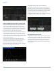
The following image shows a 1 MHz square wave being added on a
complex load with resistance, inductance and capacitance. Though the
nominal waveform shown on the AFG is a perfect square, the waveform at
the DUT has distorted a lot.
Datasheet
2 www.tektronix.com