
User's Manual


Table Of Contents
- Title page
- Table of Contents
- General Safety Summary
- Preface
- Getting Started
- Operating Basics
- Reference
- Reference
- Menu Structures
- The Setup Menu Screen
- The Graphical Waveform Editor
- The Pattern Editor
- Quick Editing
- The Table Editor
- The Equation Editor
- The Sequence Editor
- The APPL Menu
- The UTILITY Window
- External Keyboards
- Setting General Purpose Knob Direction
- Formatting a Floppy Disk
- Displaying Disk Usage
- Screen Display Enable/Disable
- Focused Color
- Displaying Instrument Status
- Internal Clock (Date and Time)
- Resetting the Instrument
- Connecting to a GPIB Network
- Ethernet Networking
- Hardcopy
- Calibration and Diagnostics
- Upgrading the System Software
- Capturing Waveforms
- Waveform Programming Language
- Command Descriptions
- Programming Examples
- File Conversion
- File Management
- FG Mode
- Waveform Mixing Mode
- Synchronous Operation Mode (AWG710B only)
- Appendices
- Appendix A: Specifications (AWG710B)
- Appendix A: Specifications (AWG710)
- Appendix B: Performance Verification (AWG710B)
- Conventions
- Self Tests
- Performance Tests
- Operating Mode Tests
- Amplitude and Offset Accuracy Tests (Normal Out), (except option 02)
- Amplitude, Offset Accuracy and Rise Time Tests (Direct DA Out), (except option 02)
- Amplitude, Offset Accuracy and Rise Time Tests (for option 02)
- Pulse Response Tests (Normal Out), (except option 02)
- Trigger Input Tests
- Event Input and Enhanced Mode Tests
- External Clock Input and VCO Out Output Tests
- VCO OUT Output Frequency and 10 MHz Reference Input Tests
- Marker Output Tests
- Synchronous Operation Tests
- Appendix B: Performance Verification (AWG710)
- Conventions
- Self Tests
- Performance Tests
- Operating Mode Tests
- Amplitude and Offset Accuracy Tests (Normal Out), (except option 02)
- Amplitude, Offset Accuracy and Rise Time Tests (Direct DA Out), (except option 02)
- Amplitude, Offset Accuracy and Rise Time Tests (for option 02)
- Pulse Response Tests (Normal Out), (except option 02)
- Trigger Input Tests
- Event Input and Enhanced Mode Tests
- 1/4 Clock Frequency and 10 MHz Reference Input Tests
- Marker Output Tests
- Appendix C: Inspection and Cleaning
- Appendix D: Sample Waveforms
- Appendix E: File Transfer Interface Outline
- Appendix F: Miscellaneous
- Appendix G: Sequence File Text Format
- Index
Appendix B: Performance Verification (AWG710B)
B-8 AWG710&AWG710B Arbitrary Waveform Generator User Manual
10. Adapter SMA (female) to N(male), 50 Ω Tektronix part number
SMA(fe)-SMA(fe)015–101
2–00 + SMA(ma)-N(ma)
015-0369-00
Signal interconnection
11. BNC–T Connector BNC (male) to BNC (female) to BNC
(female)
Tektronix part number
103–0030–00
Signal interconnection
12. Dual–Banana Connector BNC (female) to dual banana Tektronix part number
103–0090–00
Signal interconnection
13. SMA Terminator
(2 required)
50 Ω, SMA (male) Tektronix part number
015–1022–01
Signal termination
14. Precision Terminator 50 Ω, 0.1 %, BNC Tektronix part number
011–0129–00
Signal termination
15. Performance check disks Must use example listed Supplied with the product,
Tektronix part number
062–A273–00 for AWG710
063-3721-00 for AWG710B
Used to provide waveform files.
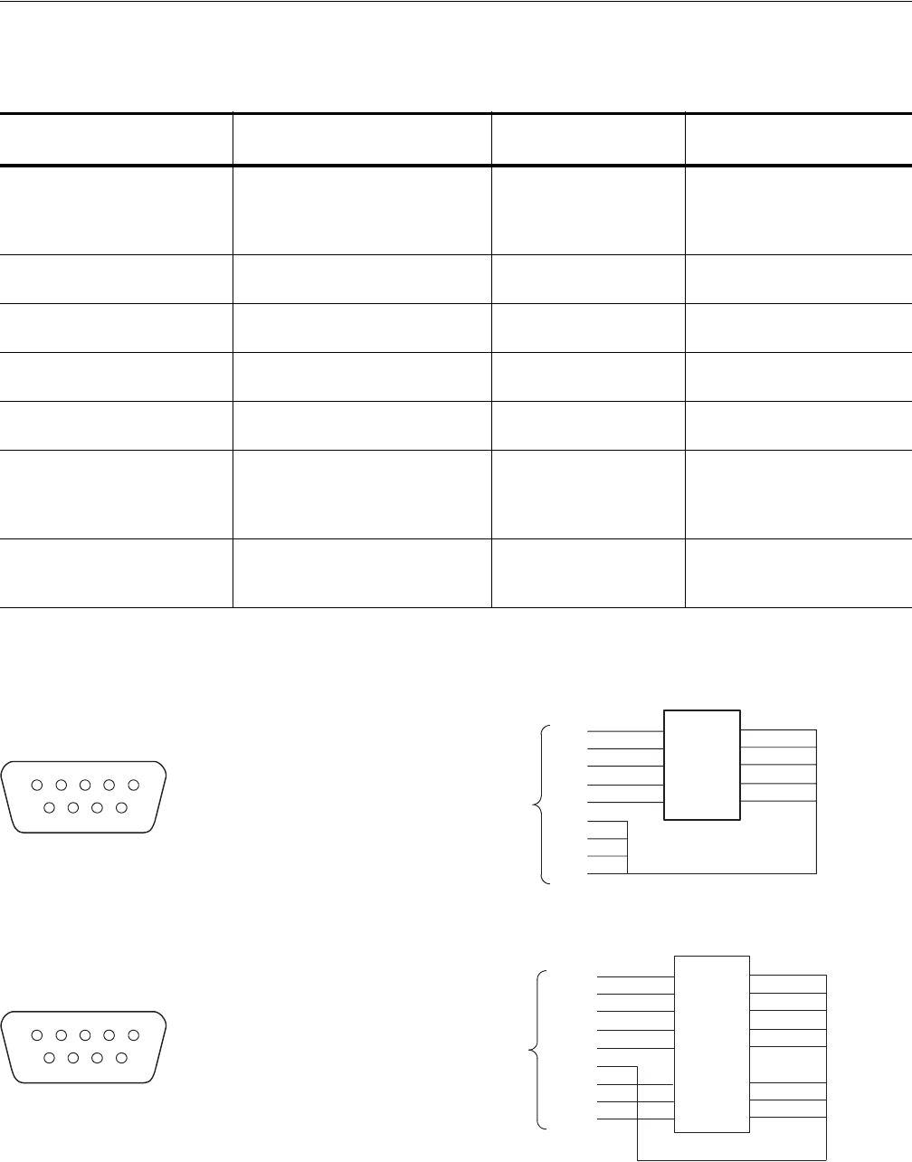
16. Ground closure (loopback
cable) with 9–pin, D–type
connector
Custom,
See Figure B-3.
Used for event mode test.
Table B-2: Test equipment (cont.)
Item number and
description Minimum requirements Example (recommended) Purpose
1STROBE
2 3 (Event Signal)
3 2 (Event Signal)
4 1 (Event Signal)
5 0 (Event Signal)
6 Signal Ground (GND)
8 Signal Ground (GND)
7 Signal Ground (GND)
9 Signal Ground (GND)
12345
9876
1
2
3
4
5
9
8
7
6
1
2
3
4
5
9
8
7
6
10
Switch ID symbols
Dip switch
SW5
SW4
SW3
SW2
SW1
9-pin, D-type,
male connector
AWG710
5
4
3
2
1
8
7
6
9
13
14
15
16
12
11
10
1
2
3
4
5
6
7
8
9
SW5
SW4
SW3
SW2
SW1
SW8
SW7
SW6
1STROBE
2 3 (Event Signal)
3 2 (Event Signal)
4 1 (Event Signal)
5 0 (Event Signal)
6 Signal Ground (GND)
8 5 (Event Signal)
7 6 (Event Signal)
9 4 (Event Signal)
12345
9876
Switch ID symbols
Dip switch
9-pin, D-type,
male connector
AWG710B