
Datasheet


Digital Phosphor Oscilloscopes
DPO4000 Series
DPO4000 • www.tektronix.com/oscilloscopes
3
Serial Triggering and Analysis
One of the most common applications
requiring long record length is serial
data analysis in embedded system
design. Embedded systems are literally
everywhere. They can contain many
different types of devices including
microprocessors, microcontrollers,
DSPs, RAM, EPROMs, FPGAs, A/Ds,
D/As and I/O. These various devices
have traditionally communicated with
each other and the outside world using
wide parallel buses. Today, however,
more and more embedded systems
are replacing these wide parallel buses
with serial buses due to less board
space required, fewer pins, lower
power, embedded clocks, differential
signaling for better noise immunity and
most importantly, lower cost. In addi-
tion, there’s a large supply of off-the-
shelf building block components from
reputable manufacturers, enabling rapid
design development. While serial buses
have a large number of benefits, they
also present significant challenges that
their predecessors (parallel buses) did
not face. They make debugging bus
and system problems more difficult, it’s
harder to isolate events of interest and
it’s more difficult to interpret what is
displayed on the oscilloscope screen.
With the optional DPO4AUTOMAX,
DPO4COMP and DPO4EMBD
modules, the DPO4000 Series
addresses these problems and repre-
sents the ultimate tool for engineers
working with low-speed serial buses
such as I
2
C, SPI, CAN, LIN, FlexRay
and RS-232/422/485/UART.
Bus Display – Provides a higher level,
combined view of the individual signals
(clock, data, chip enable, etc.) that make
up your bus, making it easy to identify
where packets begin and end and iden-
tifying sub-packet components such as
address, data, identifier, CRC, etc.
Serial Triggering – Trigger on packet
content such as start of packet,
specific addresses, specific data
content, unique identifiers, etc. on
popular low-speed serial interfaces
such as I
2
C, SPI, CAN, LIN, FlexRay
and RS-232/422/485/UART.
Bus Decoding – Tired of having to
visually inspect the waveform to count
clocks, determine if each bit is a 1 or a
0, combine bits into bytes and determine
the hex value? Let the oscilloscope do
it for you! Once you’ve set up a bus, the
oscilloscope will decode each packet
on the bus and display the value in hex,
binary, decimal (LIN and FlexRay only)
or ASCII (RS-232/422/485/UART only)
in the bus waveform.
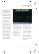
Event Table – In addition to seeing
decoded packet data on the bus wave-
form itself, you can view all captured
packets in a tabular view much like you
would see on a logic analyzer. Packets
are timestamped and listed consecu-
tively with columns for each component
(Address, Data, etc.).
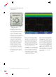
Triggering on a specific data packet going across an I
2
C bus. Yellow waveform is data, blue waveform
is clock. Bus waveform provides decoded packet content including Start, Address, Read/Write, Data,
Missing Ack and Stop.