
Datasheet


Datasheet
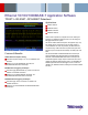
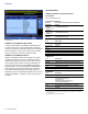
DPO4ENET 100BASE-TX decoded Event Table showing all packet information with time
stamp information.
10BASE-T and 100BASE-TX Event Table
In addition to seeing 10BASE-T and 100BASE-TX decoded data on the
bus waveform itself, you can view all captured packets in a tabular view
much like you would see in a software listing. Packets are time stamped and
listed consecutively with columns fo r each component (Time, Destination
Address, Source Address, Length, Data, FCS/CRC, and Errors).
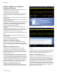
10BASE-T and 100BASE-TX Search
10BASE-T and 100BASE-TX packet content triggering is very useful for
isolating the event of interest, but once you’ve captured it and need to
analyze the surrounding data, what do you do? In the past, users had to
manually scroll through the waveform counting and converting bits and
looking for what caused the event. With a DPO4ENET Ethernet Serial
Application Module, you can enable the MDO4000 or MSO/DPO4000B
Series oscilloscope to automatically search through the acquired data
for user-defined criteria including packet content. Each occurrence is
highlighted by a search mark. Rapid navigation between marks is as simple
as pressing the Previous () and Next () buttons on the oscilloscope
front panel.
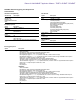
Characteristics
TDSET3 Compliance Test Characteristics
General Mask
Autofit, Waveform/Sample Count.
Instrument Compatibility
Ethernet
Standards
Recommended Oscilloscopes for Compliance
Testing
10BASE-T,
10BASE-Te,
100BASE-TX, and
1000BASE-T
1 GHz models of MSO/DPO5000, DPO7000, and
DPO/DSA/MSO70000 Series
10BASE-T,
10BASE-Te, and
100BASE-TX
500 MHz models of MSO/DPO5000, DPO7000, and
DPO/DSA/MSO70000 Series
10BASE-T and
10BASE-Te
All models of MSO/DPO5000, DPO7000, and
DPO/DSA/MSO70000 Series
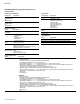
10BASE-T/10BASE-Te
Test Description
Template
MAU Ext (and inverted), MAU Int (and inverted), Link Pulse,
and TP_IDL
MAU Template
Scale
0.9 and 1.1
Amplitude
Differential voltage, common mode output voltage
Harmonic
Content of ones
Jitter With and without cable
Return Loss
85, 100, 111 *
1
100BASE-TX
Test Description
Template Positive and negative polarity
Amplitude
Signal amplitude, amplitude symmetry, differential output
voltage, waveform overshoot
Time Domain Tests
Rise Time, Fall Time, Rise/Fall Time Symmetry
Jitter Jitter and duty cycle distortion
Return Loss
85, 100, 115 *
1
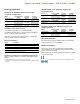
1000BASE-T
Test Description
Template
Points A, B, C, D, F, H
Amplitude
Peak voltage (points A, B)
Level Accuracy (points B, C, D)
Droop (points G, J)
Distortion (with and without TX_TCLK*
2
)
Common Mode Output Voltage
Disturber Options
With and without disturber signal
Jitter
Master (filtered and unfiltered), Slave*
3
(filtered and
unfiltered)
Return Loss
85, 100, 115 *
1
*
1
85 and 115 plots require four-channel oscilloscopes.
*
2
If clock inaccuracy is high, results may vary on some oscilloscopes due to limitations on the segmented
memory acquisitions.
*
3
Slave-filtered tests require four-channel oscilloscopes.
6 www.tektronix.com