
User's Manual

Performance Tests
4–64
TDS 684A, TDS 744A, & TDS 784A Service Manual
H Adjust the output of the DC calibration generator until it precisely
overlaps the top (upper) level of the stored probe compensation
signal. (This value will be near 500 mV.)
H Record the setting of the DC generator.
H Adjust the output of the DC calibration generator until it precisely
overlaps the base (lower) level of the stored probe compensation
signal. (This value will be near zero volts.)
H Record the setting of the DC generator.
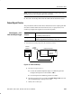
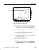
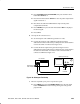
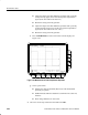
f. Press CLEAR MENU to remove the menus from the display. See
Figure 4–24.
Figure 4–24: Measurement of Probe Compensator Amplitude
g. Check against limits:
H Subtract the value just obtained (base level) from that obtained
previously (top level).
H CHECK that the difference obtained is within 495 mV to 505 mV,
inclusive.
H Enter voltage difference on test record.
3. Disconnect the hookup: Disconnect the cable from CH 1.