
User's Manual


Adjustment Procedures
TDS 684A, TDS 744A, & TDS 784A Service Manual
5–15
a. Display and measure the test signal:
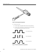
H Monitor the CH 1 Pk-Pk readout while you set the output of the
generator for a 3.0 V (6 division), 6 MHz reference signal.
H Set the horizontal SCALE to 1 ns and set the frequency of the
generator to 500 MHz.
H Read the measurement results at the CH 1 Pk-Pk readout on screen.
b. Check against limits: CHECK that the CH 1 Pk-Pk readout is greater
than or equal to 2.1 V.
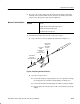
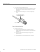
3. Disconnect the hookup:
a. Unplug the probe from BNC-to-probe tip adapter.
b. If substep 2b was passed, the probe adjustment is finished. Reverse the
instructions in Figure 5–5, page 5–13, to reinstall the retractable hook
probe tip.
c. If substep 2b was not passed, leave the probe tip exposed. Remove the
probe from CH 1 and go on to the next procedure Adjust the Probe —
High Frequency Response.
Do not perform this procedure until you have first completed the procedures
Compensate the Probe and Measure Probe Bandwidth on pages 5–10 and 5–13,
respectively.
Do not perform this procedure if you have successfully completed Measure
Probe Bandwidth. Probe adjustment is complete.
Equipment
Required
One calibration generator (Item 11)
One 50 precision cable (Item 9)
One tunnel diode pulser (Item 29)
One BNC female-to-female adapter (Item 1)
One BNC to probe adapter (Item 2)
One 10X attenuator (Item 5)
One P6139A 10X probe (Item 17)
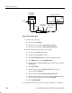
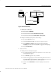
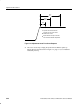
1. Install the test hookup and preset the oscilloscope controls:
Adjust the Probe — High
Frequency Response