
User's Manual


Removal and Installation Procedures
TDS 684A, TDS 744A, & TDS 784A Service Manual
6–33
b. Locate the modules to be removed in the locator diagram Outer-Chassis
Modules, Figure 6–2, page 6–13. See also the A29 Video Trigger Board
on Figure 6–15, page 6–35.
c. Do the procedures A14 D1 Bus and Analog-Power and Digital-Power
Cables and A23 SerPar Board that precede this procedure to remove
those items. It is not necessary to pull the A23 board assembly out
entirely nor is it necessary to remove the cable connector from the A23
SerPar board to the A11 Processor/Display board
2. Orient the oscilloscope: Set the oscilloscope so its bottom is down on the
work surface and its front is facing you.
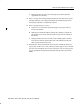
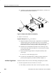
3. Remove the A29 Video Trigger board: Figure 6–14 shows the A29 Video
Trigger board (option 05) installed.
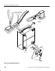
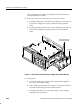
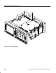
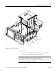
a. Remove (or pull loose) the A27 Connector board (see number 3 on
Figure 6–15).
b. Slide back and lift up the Video Trigger circuit board (see FigureĂ6–15).