
User's Manual

Removal and Installation Procedures
6–52
TDS 684A, TDS 744A, & TDS 784A Service Manual
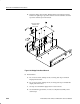
H A14 D1 Bus and Analog-Power and Digital-Power Cables
(page 6–29)
H Front Cover, Trim Ring, Menu Buttons, and Attenuator Panel
(page 6–22)
H Rear Cover and Cabinet (page 6–18)
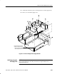
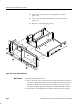
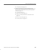
Figure 6–24: Front Subpanel Removal
Additional Modules Removed: All.
1. Remove the main chassis: Since the removal of the main chassis requires the
removal of virtually all modules, do the procedure Disassembly for Cleaning
that follows. While doing Disassembly for Cleaning, you will remove the
front-panel assembly. Ignore the instructions to disassemble that assembly.
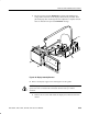
2. Reinstallation: See reinstallation instructions in Disassembly for Cleaning.
Main Chassis