
User's Manual


Theory of Operation
TDS 684A, TDS 744A, & TDS 784A Service Manual
3–3
The processor system sends instructions to and receives information from the
Front Panel Processor on the A12 Front Panel board. The Front Panel Processor
reads the front-panel switches and potentiometers. Any changes in their settings
are reported to the processor system. The Front Panel Processor also turns the
LEDs on and off and generates the bell signal.
Front-panel menu switches are also read by the Front Panel Processor. The
processor sends any changes in menu selections to the processor system. The
ON/STBY switch is one of the menu switches. However, it is not read by the
Front Panel Processor, but passes through the A12 Front Panel board and the
A11 DRAM Processor/Display board to the low voltage power supply.
The front panel also generates the probe compensation signals SIGNAL
and GND.
The GPIB connector provides access to stored waveforms, and allows external
control of the oscilloscope.
You can make hardcopies on the GPIB, RS-232 and Centronics ports.
The low voltage power supply is a switching power converter with active power
factor control. It supplies power to all of the circuitry in the oscilloscope.
The principal POWER switch, located on the rear panel, controls all power to
the oscilloscope including the Low Voltage Power Supply. The ON/STBY
switch, located on the front panel, also controls all of the power to the oscillo-
scope except for part of the circuitry in the Low Voltage Power Supply.
The power supply sends a power fail (~PF) warning to the processor system if
the power is going down.
The fan provides forced air cooling for the oscilloscope. It connects to +25 V
from the Low Voltage Power Supply by way of the A11 DRAM Processor/Dis-
play module.
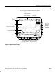
Front Panel
Rear Panel
Low Voltage Power Supply
Fan