
User Manual
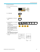
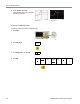
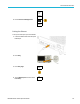
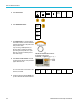
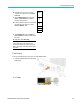
Table Of Contents
- toc
- Important safety information
- Compliance information
- Preface
- Installation
- Before Installation
- Operating Considerations
- Connecting Probes
- Securing the Oscilloscope
- Powering on the Oscilloscope
- Powering off the Oscilloscope
- Functional Check
- Compensating a TPP0250, TPP0500B or TPP1000 Passive Voltage Prob
- Compensating a non-TPP0250, non-TPP0500B or non-TPP1000 Passive
- Application Module Free Trial
- Installing an Application Module
- Upgrading Bandwidth
- Changing the Language of the User Interface or Keyboard
- Changing the Date and Time
- Signal Path Compensation
- Upgrading Firmware
- Connecting Your Oscilloscope to a Computer
- Connecting a USB Keyboard to Your Oscilloscope
- Get Acquainted with the Instrument
- Acquire the Signal
- Setting Up Analog Channels
- Using the Default Setup
- Using Autoset
- Acquisition Concepts
- Using FastAcq
- How the Analog Acquisition Modes Work
- Changing the Acquisition Mode, Record Length, and Delay Time
- Using Roll Mode
- Act on Event
- Setting Up a Serial or Parallel Bus
- Setting Up Digital Channels
- When and Why to Turn On MagniVu
- Using MagniVu
- Setting Up the RF Inputs
- Trigger Setup
- Display Waveform or Trace Data
- Adding and Removing a Waveform
- Setting the Display Style and Persistence
- Setting Waveform Intensity
- Scaling and Positioning a Waveform
- Setting Input Parameters
- Positioning and Labeling Bus Signals
- Positioning, Scaling, and Grouping Digital Channels
- Viewing Digital Channels
- Annotating the Screen
- Viewing the Trigger Frequency
- Displaying the Frequency Domain Menu
- Analyze Waveform or Trace Data
- Using Markers in the Frequency Domain
- Taking Automatic Measurements in the Time Domain
- Selecting Automatic Measurements in the Time Domain
- Customizing an Automatic Measurement in the Time Domain
- Taking Automatic Measurements in the Frequency Domain
- Taking Digital Voltmeter Measurements
- Taking Manual Measurements with Cursors
- Setting Up a Histogram
- Using Math Waveforms
- Using FFT
- Using Advanced Math
- Using Spectrum Math
- Using Reference Waveforms and Traces
- Using Wave Inspector to Manage Long Record Length Waveforms
- Auto-magnify
- Limit and Mask Testing
- Making Video Tests
- Making Automated Power Measurements
- Save and Recall Information
- Use the Arbitrary Function Generator
- Use the Application Modules
- Appendix A: Warranted Specifications
- Appendix B: TPP0250, TPP0500B and TPP1000: 250€MHz, 500€MHz and
- Appendix C: P6316 General-Purpose Logic Probe Information
- Appendix D: OpenSSL License

Save and Recall I
nformation
3. From the resulting side menu, set the following:
Setting Description
Drive Letter
Select from I:
to Z:
Server Name o
r IP Address
UseaUSBkeyb
oard or the on-screen interface to enter the server name or IP
address.
Path
Use a USB keyboard or the on-screen interface to enter the shared file path.
For example, to mount an MS Windows PC directory named “C:\Example”, enter
“C$\Exampl
e”. The dollar sign enables sharing. No colon is needed.
User Name
If necessa
ry, use a USB keyboard or the on-screen interface to enter the user name.
User Password
If necessa
ry, use a USB keyboard or the on-screen interface to enter the user
password. The oscilloscope only displays “*”'s as you type the password. They are
erased from the screen after OK Accept is pushed.
NOTE. Ensure that file sharing is enabled for the network location.
4. Push OK Accept.
NOTE. T
o unmount a network drive, push Save/Recall Menu on the front panel, push File Utilities on the lower menu, push
–more–1of2on the side menu, and Unmount items.
NOTE. Any network locations that were mounted when the oscilloscope was powered down will be automatically remounted
when the oscilloscope is powered up. Unmount any network location that you do not want to automatically remount
on pow
er up.
Printing a Hard Copy
To print an image of what appears on the oscillo scope screen, do the following procedure.
Connect a Printer to Your Oscilloscope
Connect a non-PictBridge printer to a USB port on the rear or front panel of the oscilloscope. Alternatively, connect a
Pi
ctBridge printer to the USB device port on the rear panel, or hook up a networked printer through the Ethernet port.
NOTE. Refer to the www.tektronix.com/printer_setup Web page for a list of compatible printers.
172 MDO3000 Series Oscilloscopes User Manual