
User Manual
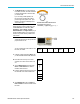
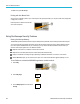
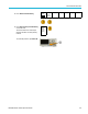
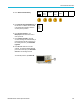
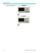
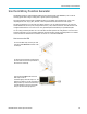
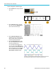
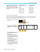
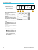
Table Of Contents
- toc
- Important safety information
- Compliance information
- Preface
- Installation
- Before Installation
- Operating Considerations
- Connecting Probes
- Securing the Oscilloscope
- Powering on the Oscilloscope
- Powering off the Oscilloscope
- Functional Check
- Compensating a TPP0250, TPP0500B or TPP1000 Passive Voltage Prob
- Compensating a non-TPP0250, non-TPP0500B or non-TPP1000 Passive
- Application Module Free Trial
- Installing an Application Module
- Upgrading Bandwidth
- Changing the Language of the User Interface or Keyboard
- Changing the Date and Time
- Signal Path Compensation
- Upgrading Firmware
- Connecting Your Oscilloscope to a Computer
- Connecting a USB Keyboard to Your Oscilloscope
- Get Acquainted with the Instrument
- Acquire the Signal
- Setting Up Analog Channels
- Using the Default Setup
- Using Autoset
- Acquisition Concepts
- Using FastAcq
- How the Analog Acquisition Modes Work
- Changing the Acquisition Mode, Record Length, and Delay Time
- Using Roll Mode
- Act on Event
- Setting Up a Serial or Parallel Bus
- Setting Up Digital Channels
- When and Why to Turn On MagniVu
- Using MagniVu
- Setting Up the RF Inputs
- Trigger Setup
- Display Waveform or Trace Data
- Adding and Removing a Waveform
- Setting the Display Style and Persistence
- Setting Waveform Intensity
- Scaling and Positioning a Waveform
- Setting Input Parameters
- Positioning and Labeling Bus Signals
- Positioning, Scaling, and Grouping Digital Channels
- Viewing Digital Channels
- Annotating the Screen
- Viewing the Trigger Frequency
- Displaying the Frequency Domain Menu
- Analyze Waveform or Trace Data
- Using Markers in the Frequency Domain
- Taking Automatic Measurements in the Time Domain
- Selecting Automatic Measurements in the Time Domain
- Customizing an Automatic Measurement in the Time Domain
- Taking Automatic Measurements in the Frequency Domain
- Taking Digital Voltmeter Measurements
- Taking Manual Measurements with Cursors
- Setting Up a Histogram
- Using Math Waveforms
- Using FFT
- Using Advanced Math
- Using Spectrum Math
- Using Reference Waveforms and Traces
- Using Wave Inspector to Manage Long Record Length Waveforms
- Auto-magnify
- Limit and Mask Testing
- Making Video Tests
- Making Automated Power Measurements
- Save and Recall Information
- Use the Arbitrary Function Generator
- Use the Application Modules
- Appendix A: Warranted Specifications
- Appendix B: TPP0250, TPP0500B and TPP1000: 250€MHz, 500€MHz and
- Appendix C: P6316 General-Purpose Logic Probe Information
- Appendix D: OpenSSL License
Use the Arbitrar
y Function Generator
If needed, push AFG > Waveform Edit to bring
up the waveform edit lower menu.
5. Push Edit Existing to change, add, or delete
points in a cu
rrent waveform.
Edit
Existing
Create
New
Load
Waveform
Freq.
Ampl.
Offset
100.00kHz
500.00m-
Vpp
0.000 V
Period
10.000 s
High
250.00mV
Low –250.
00mV
Save
Waveform
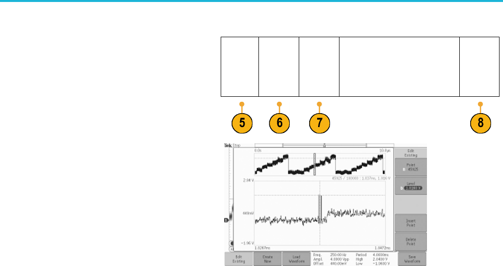
When you enable the internal editor, the screen
splits into
a smaller top window and a larger
bottom window.
The smaller, top part of the screen becomes
an overvie
w, which shows the entire waveform
memory. A box shows the zoomed-in portion of
the waveform.
The large
r, lower part becomes the zoomed-in
view of the overview, as defined by the box in the
top part of the screen. This lower part shows up
to 500 poi
nts of the record.
Turn the Multipurpose a knob to select a point
to edit.
Turn the
Multipurpose b knob to set the voltage
level of that point. The voltage level is a function
of the current amplitude and offset settings for
the wav
eform.
Use the side menu items to add or remove points
from the waveform.
6. Push Create New from the lower-menu to
make a fresh arbitrary waveform.
On the
resulting side menu, turn
Multipurpose a or use the keypad to defi ne
the number of points in the waveform. Your
wave
form can have up to 131,072 points.
Turn Multipurpose b to choose the basic
function. Choose between square, sine,
ramp
, pulse, and noise.
Push OK Create to build the new waveform.
188 MDO3000 Series Oscilloscopes User Manual