
User Manual
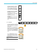
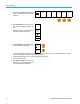
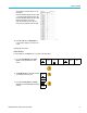
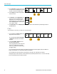
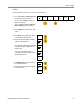
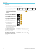
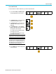
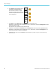
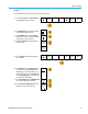
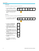
Table Of Contents
- toc
- Important safety information
- Compliance information
- Preface
- Installation
- Before Installation
- Operating Considerations
- Connecting Probes
- Securing the Oscilloscope
- Powering on the Oscilloscope
- Powering off the Oscilloscope
- Functional Check
- Compensating a TPP0250, TPP0500B or TPP1000 Passive Voltage Prob
- Compensating a non-TPP0250, non-TPP0500B or non-TPP1000 Passive
- Application Module Free Trial
- Installing an Application Module
- Upgrading Bandwidth
- Changing the Language of the User Interface or Keyboard
- Changing the Date and Time
- Signal Path Compensation
- Upgrading Firmware
- Connecting Your Oscilloscope to a Computer
- Connecting a USB Keyboard to Your Oscilloscope
- Get Acquainted with the Instrument
- Acquire the Signal
- Setting Up Analog Channels
- Using the Default Setup
- Using Autoset
- Acquisition Concepts
- Using FastAcq
- How the Analog Acquisition Modes Work
- Changing the Acquisition Mode, Record Length, and Delay Time
- Using Roll Mode
- Act on Event
- Setting Up a Serial or Parallel Bus
- Setting Up Digital Channels
- When and Why to Turn On MagniVu
- Using MagniVu
- Setting Up the RF Inputs
- Trigger Setup
- Display Waveform or Trace Data
- Adding and Removing a Waveform
- Setting the Display Style and Persistence
- Setting Waveform Intensity
- Scaling and Positioning a Waveform
- Setting Input Parameters
- Positioning and Labeling Bus Signals
- Positioning, Scaling, and Grouping Digital Channels
- Viewing Digital Channels
- Annotating the Screen
- Viewing the Trigger Frequency
- Displaying the Frequency Domain Menu
- Analyze Waveform or Trace Data
- Using Markers in the Frequency Domain
- Taking Automatic Measurements in the Time Domain
- Selecting Automatic Measurements in the Time Domain
- Customizing an Automatic Measurement in the Time Domain
- Taking Automatic Measurements in the Frequency Domain
- Taking Digital Voltmeter Measurements
- Taking Manual Measurements with Cursors
- Setting Up a Histogram
- Using Math Waveforms
- Using FFT
- Using Advanced Math
- Using Spectrum Math
- Using Reference Waveforms and Traces
- Using Wave Inspector to Manage Long Record Length Waveforms
- Auto-magnify
- Limit and Mask Testing
- Making Video Tests
- Making Automated Power Measurements
- Save and Recall Information
- Use the Arbitrary Function Generator
- Use the Application Modules
- Appendix A: Warranted Specifications
- Appendix B: TPP0250, TPP0500B and TPP1000: 250€MHz, 500€MHz and
- Appendix C: P6316 General-Purpose Logic Probe Information
- Appendix D: OpenSSL License
Acquire the Sign
al
CAN, CAN FD BUS
To acquire data from a CAN or CAN FD bus, you need to set up these items:
1. If you selected CAN, push Define Inputs
and the appropriate side menu choices.
Bus B1
CAN
Define
Inputs
Thresh-
olds
Configure
500 Kbps
B1 Label
CAN
Bus
Display
Event Table
2. Turn Multipurpose a to select the channel
connected to the CA N bus source.
CAN Input
(a) 1
3. Turn Multipurpose a to select the type of
CAN signal: CAN_H, CAN_L, Rx, Tx, or
Differential.
Signal
Type
CAN_H
4. Turn Multipurp ose a to set the Sample
Point to a percentage of the position within
the bit period or the unit interval.
Sample
Point
50%
For a CAN 2.0 bus the allowable sample
point range is 5% to 95%.
For a CAN FD bus the allowable sample
point range is 15% to 95%.
NOTE. CAN FD requires an accurately specified
sample point for correct decode and triggering..
NOTE. CAN FD uses the same sample point
percentage for bits transmitted at SD bit rates
and FD bit rates. For optimal performance, set
the s ample point to the value used for SD bits
(the "Arbitration Phase" sample point).
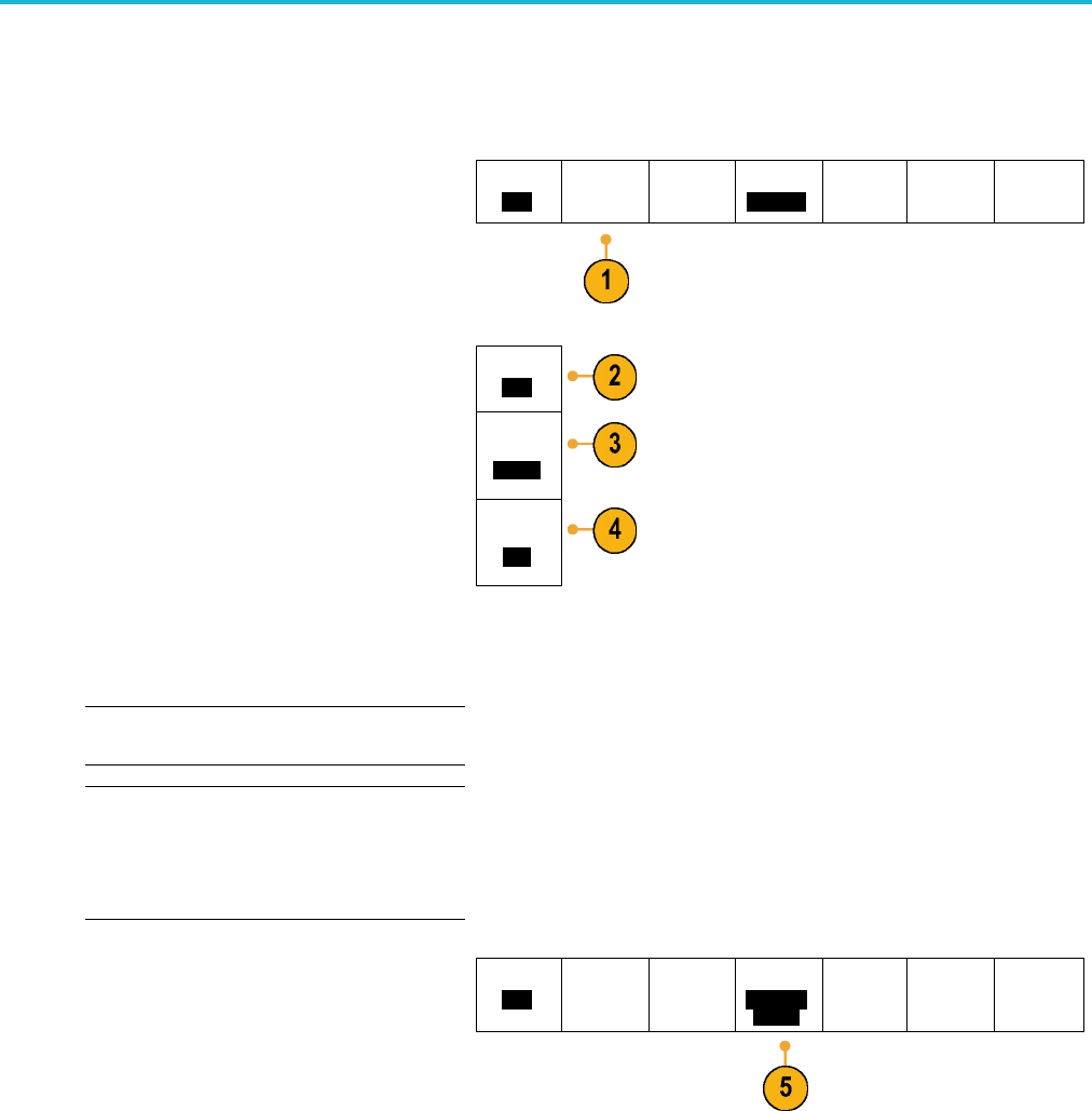
5. Push Configure and select the appropriate
side menu choices..
Bus B1
CAN
Define
Inputs
Thresh-
olds
Configure
500 Kbps
4 Mbps
B1 Label
CAN
Bus
Display
Event Table
MDO3000 Series Oscilloscopes User Manual 75