
User Manual
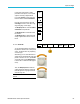
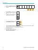
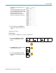
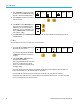

Table Of Contents
- toc
- Important safety information
- Compliance information
- Preface
- Installation
- Before Installation
- Operating Considerations
- Connecting Probes
- Securing the Oscilloscope
- Powering on the Oscilloscope
- Powering off the Oscilloscope
- Functional Check
- Compensating a TPP0250, TPP0500B or TPP1000 Passive Voltage Prob
- Compensating a non-TPP0250, non-TPP0500B or non-TPP1000 Passive
- Application Module Free Trial
- Installing an Application Module
- Upgrading Bandwidth
- Changing the Language of the User Interface or Keyboard
- Changing the Date and Time
- Signal Path Compensation
- Upgrading Firmware
- Connecting Your Oscilloscope to a Computer
- Connecting a USB Keyboard to Your Oscilloscope
- Get Acquainted with the Instrument
- Acquire the Signal
- Setting Up Analog Channels
- Using the Default Setup
- Using Autoset
- Acquisition Concepts
- Using FastAcq
- How the Analog Acquisition Modes Work
- Changing the Acquisition Mode, Record Length, and Delay Time
- Using Roll Mode
- Act on Event
- Setting Up a Serial or Parallel Bus
- Setting Up Digital Channels
- When and Why to Turn On MagniVu
- Using MagniVu
- Setting Up the RF Inputs
- Trigger Setup
- Display Waveform or Trace Data
- Adding and Removing a Waveform
- Setting the Display Style and Persistence
- Setting Waveform Intensity
- Scaling and Positioning a Waveform
- Setting Input Parameters
- Positioning and Labeling Bus Signals
- Positioning, Scaling, and Grouping Digital Channels
- Viewing Digital Channels
- Annotating the Screen
- Viewing the Trigger Frequency
- Displaying the Frequency Domain Menu
- Analyze Waveform or Trace Data
- Using Markers in the Frequency Domain
- Taking Automatic Measurements in the Time Domain
- Selecting Automatic Measurements in the Time Domain
- Customizing an Automatic Measurement in the Time Domain
- Taking Automatic Measurements in the Frequency Domain
- Taking Digital Voltmeter Measurements
- Taking Manual Measurements with Cursors
- Setting Up a Histogram
- Using Math Waveforms
- Using FFT
- Using Advanced Math
- Using Spectrum Math
- Using Reference Waveforms and Traces
- Using Wave Inspector to Manage Long Record Length Waveforms
- Auto-magnify
- Limit and Mask Testing
- Making Video Tests
- Making Automated Power Measurements
- Save and Recall Information
- Use the Arbitrary Function Generator
- Use the Application Modules
- Appendix A: Warranted Specifications
- Appendix B: TPP0250, TPP0500B and TPP1000: 250€MHz, 500€MHz and
- Appendix C: P6316 General-Purpose Logic Probe Information
- Appendix D: OpenSSL License
Acquire the Sign
al
FlexRay Bus
To acquire data from a FlexRay bus, you need to also set up these items:
1. If you selected FlexRay , push Define
Inputs and the desired side menu choices.
Bus B1
FlexRay
Define
Inputs
Thresholds Bit Rate B1 Label
FlexRay
FlexRay
Bus
Display
Event
Table
2. A s appropriate, push the Threshold, Bit Rate,
Label, Bus Display and Event Table buttons
and set their corresponding parameter
values.
Audio Bus
To acquire data from an Audio bus, you need to also set up these items:
1. If you sele
cted Audio, push Define Inputs
and the desired side menu choices.
Bus B1
Audio
Define
Inputs
Thresholds
Configure
B1 Label
RS-232
Bus
Display
Event
Table
2. Push Typ
e, and turn Multipurpose a
to select the type of audio bus data
configuration on which to trigger.
Audio Bu
s
Type
3. Select I2S to trigger on the standard Inter-IC
Sound, or Integrated Interchip Sound,
electr
ical serial bus interface standard stereo
format.
I2S
4. Selec
t Left Justified to trigger on an I2S
stream where there is no bit clock delay and
the data starts right on the edge of the word
sele
ct clock.
Left
Justified
(LJ)
5. Select Right Justified to trigger on an I2S
stre
am where the data lines up with the right
edge of the word select clock.
Right
Justified
(RJ)
6. Sel
ect TDM to trigger on time-division
multiplexing.
TDM
7. Pu
sh Configure, and the appropriate
buttons on the side menu to further set up
I2S triggering.
78 MDO3000 Series Oscilloscopes User Manual