
User Manual
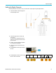

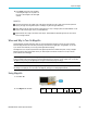
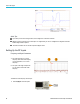
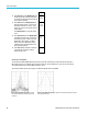
Table Of Contents
- toc
- Important safety information
- Compliance information
- Preface
- Installation
- Before Installation
- Operating Considerations
- Connecting Probes
- Securing the Oscilloscope
- Powering on the Oscilloscope
- Powering off the Oscilloscope
- Functional Check
- Compensating a TPP0250, TPP0500B or TPP1000 Passive Voltage Prob
- Compensating a non-TPP0250, non-TPP0500B or non-TPP1000 Passive
- Application Module Free Trial
- Installing an Application Module
- Upgrading Bandwidth
- Changing the Language of the User Interface or Keyboard
- Changing the Date and Time
- Signal Path Compensation
- Upgrading Firmware
- Connecting Your Oscilloscope to a Computer
- Connecting a USB Keyboard to Your Oscilloscope
- Get Acquainted with the Instrument
- Acquire the Signal
- Setting Up Analog Channels
- Using the Default Setup
- Using Autoset
- Acquisition Concepts
- Using FastAcq
- How the Analog Acquisition Modes Work
- Changing the Acquisition Mode, Record Length, and Delay Time
- Using Roll Mode
- Act on Event
- Setting Up a Serial or Parallel Bus
- Setting Up Digital Channels
- When and Why to Turn On MagniVu
- Using MagniVu
- Setting Up the RF Inputs
- Trigger Setup
- Display Waveform or Trace Data
- Adding and Removing a Waveform
- Setting the Display Style and Persistence
- Setting Waveform Intensity
- Scaling and Positioning a Waveform
- Setting Input Parameters
- Positioning and Labeling Bus Signals
- Positioning, Scaling, and Grouping Digital Channels
- Viewing Digital Channels
- Annotating the Screen
- Viewing the Trigger Frequency
- Displaying the Frequency Domain Menu
- Analyze Waveform or Trace Data
- Using Markers in the Frequency Domain
- Taking Automatic Measurements in the Time Domain
- Selecting Automatic Measurements in the Time Domain
- Customizing an Automatic Measurement in the Time Domain
- Taking Automatic Measurements in the Frequency Domain
- Taking Digital Voltmeter Measurements
- Taking Manual Measurements with Cursors
- Setting Up a Histogram
- Using Math Waveforms
- Using FFT
- Using Advanced Math
- Using Spectrum Math
- Using Reference Waveforms and Traces
- Using Wave Inspector to Manage Long Record Length Waveforms
- Auto-magnify
- Limit and Mask Testing
- Making Video Tests
- Making Automated Power Measurements
- Save and Recall Information
- Use the Arbitrary Function Generator
- Use the Application Modules
- Appendix A: Warranted Specifications
- Appendix B: TPP0250, TPP0500B and TPP1000: 250€MHz, 500€MHz and
- Appendix C: P6316 General-Purpose Logic Probe Information
- Appendix D: OpenSSL License
Acquire the Sign
al
Amplitude
2. Push Ref Level and turn Multipurpose a to
set the approx
imate maximum power level,
as shown by the baseline indicator at the top
of the frequency graticule.
Ref Level
(a)
-25.0 dBm
3. Push Vertica
l and turn M ultipu rpose a to
adjust the vertical position. You will move
the baseline indicator up or down. This is
useful if yo
u want to move signals onto the
visible display.
Turn Multipu rpo se b to adjust the vertical
scale.
Vertical
420 mdiv
20.0 dB/div
4. Push Vertical Units and turn Multipurp ose
a to define the vertical units of measure for
the frequ
ency domain. Choices are: dBm,
dBW, dBmV, dBV, dBmA , and dBA.
This is useful if your application requires
adiffere
nt unit of measurement than that
being currently displayed.
Vertical
Units
dBm
5. Push Auto Level to direct the o scilloscope
to autom
atically calculate and set the
reference level for you.
Auto Level
Resolution Bandwidth
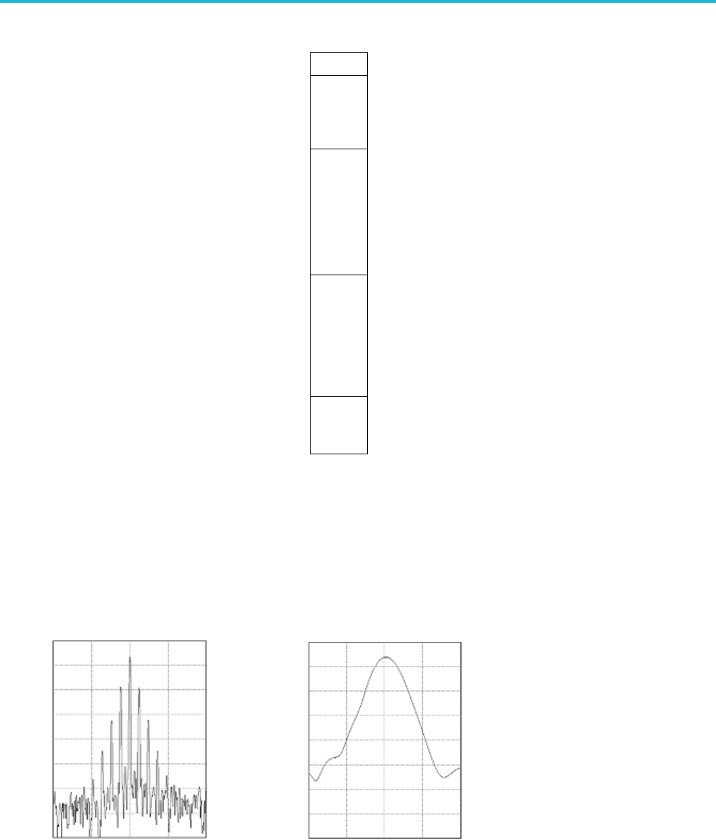
The resolution bandwidth (RBW) determines the level to which the oscilloscope can resolve individual frequencies in
the frequency domain. For example, if the test signal contains two carriers separated by 1 kHz, you will not be able to
discriminate between them unless the RBW is less than 1 kHz.
The views below both show the s ame signal. The difference between them is their RBW.
Lower (narrower) RBWs take longer to process,
but have finer frequency resolution and a lower
noise floor.
Higher (wider ) RBWs take less ti m e to process, but have less frequency resolution
and a higher noise floor.
86 MDO3000 Series Oscilloscopes User Manual