
User Manual
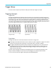
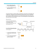
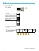
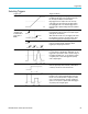
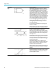
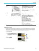
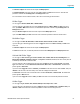
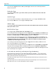
Table Of Contents
- toc
- Important safety information
- Compliance information
- Preface
- Installation
- Before Installation
- Operating Considerations
- Connecting Probes
- Securing the Oscilloscope
- Powering on the Oscilloscope
- Powering off the Oscilloscope
- Functional Check
- Compensating a TPP0250, TPP0500B or TPP1000 Passive Voltage Prob
- Compensating a non-TPP0250, non-TPP0500B or non-TPP1000 Passive
- Application Module Free Trial
- Installing an Application Module
- Upgrading Bandwidth
- Changing the Language of the User Interface or Keyboard
- Changing the Date and Time
- Signal Path Compensation
- Upgrading Firmware
- Connecting Your Oscilloscope to a Computer
- Connecting a USB Keyboard to Your Oscilloscope
- Get Acquainted with the Instrument
- Acquire the Signal
- Setting Up Analog Channels
- Using the Default Setup
- Using Autoset
- Acquisition Concepts
- Using FastAcq
- How the Analog Acquisition Modes Work
- Changing the Acquisition Mode, Record Length, and Delay Time
- Using Roll Mode
- Act on Event
- Setting Up a Serial or Parallel Bus
- Setting Up Digital Channels
- When and Why to Turn On MagniVu
- Using MagniVu
- Setting Up the RF Inputs
- Trigger Setup
- Display Waveform or Trace Data
- Adding and Removing a Waveform
- Setting the Display Style and Persistence
- Setting Waveform Intensity
- Scaling and Positioning a Waveform
- Setting Input Parameters
- Positioning and Labeling Bus Signals
- Positioning, Scaling, and Grouping Digital Channels
- Viewing Digital Channels
- Annotating the Screen
- Viewing the Trigger Frequency
- Displaying the Frequency Domain Menu
- Analyze Waveform or Trace Data
- Using Markers in the Frequency Domain
- Taking Automatic Measurements in the Time Domain
- Selecting Automatic Measurements in the Time Domain
- Customizing an Automatic Measurement in the Time Domain
- Taking Automatic Measurements in the Frequency Domain
- Taking Digital Voltmeter Measurements
- Taking Manual Measurements with Cursors
- Setting Up a Histogram
- Using Math Waveforms
- Using FFT
- Using Advanced Math
- Using Spectrum Math
- Using Reference Waveforms and Traces
- Using Wave Inspector to Manage Long Record Length Waveforms
- Auto-magnify
- Limit and Mask Testing
- Making Video Tests
- Making Automated Power Measurements
- Save and Recall Information
- Use the Arbitrary Function Generator
- Use the Application Modules
- Appendix A: Warranted Specifications
- Appendix B: TPP0250, TPP0500B and TPP1000: 250€MHz, 500€MHz and
- Appendix C: P6316 General-Purpose Logic Probe Information
- Appendix D: OpenSSL License
Trigger Setup
Trigger Setup
This section contains concepts and procedures for setting up the oscilloscope to trigger on your signal.
Triggering Concepts
Trigger Event
The trigger event establishes the time-reference point in the waveform record. All waveform record data is located in time
with respect to that point. The instrument continuously acquires and retains enough sample points to fill the pretrigger portion
of the waveform record. That is the part of the waveform that is displayed before, or to the left of, the triggering event on
screen. When a trigger event occurs, the instrument starts acquiring samples to build the posttrigger portion of the waveform
record, that is, the part displayed after or to the right of the trigger event. After a trigger is recognized, the instrument will not
accept another trigger until the acquisition is complete and the holdoff time has expired.
Untrigg
ered display
Trigger
ed disp lay
Trigger Modes
The trigger mode determines how the instrument behaves in the absence of a trigger event:
Normal trigger mode enables the instrument to acquire a waveform only when it is triggered. If no trigger occurs, the last
waveform record acquired remains on the display. If no last w aveform exists, no waveform is displayed.
Auto trigger mode enables the instrument to acquire a waveform even if a trigger does not occur. Auto mode uses a
timer that starts when the acquisition is started, and the pretrigger information is obtained. If a trigger event is not
detected before the timer times out, the instrument forces a trigger. The length of time it waits for a trigger event
depends on the time base setting.
Auto mode, when forcing triggers in the absence of valid triggering events, does not synchronize the waveform on the
display. The waveform will appear to roll across the screen. If valid triggers occur, the display will become stable.
You can also force the instrument to trigger by pushing the front panel Force Trig button.
MDO3000 Series Oscilloscopes User Manual 89