
User Manual
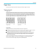
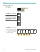
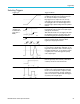
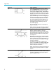
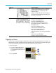
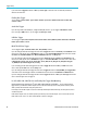
Table Of Contents
- toc
- Important safety information
- Compliance information
- Preface
- Installation
- Before Installation
- Operating Considerations
- Connecting Probes
- Securing the Oscilloscope
- Powering on the Oscilloscope
- Powering off the Oscilloscope
- Functional Check
- Compensating a TPP0250, TPP0500B or TPP1000 Passive Voltage Prob
- Compensating a non-TPP0250, non-TPP0500B or non-TPP1000 Passive
- Application Module Free Trial
- Installing an Application Module
- Upgrading Bandwidth
- Changing the Language of the User Interface or Keyboard
- Changing the Date and Time
- Signal Path Compensation
- Upgrading Firmware
- Connecting Your Oscilloscope to a Computer
- Connecting a USB Keyboard to Your Oscilloscope
- Get Acquainted with the Instrument
- Acquire the Signal
- Setting Up Analog Channels
- Using the Default Setup
- Using Autoset
- Acquisition Concepts
- Using FastAcq
- How the Analog Acquisition Modes Work
- Changing the Acquisition Mode, Record Length, and Delay Time
- Using Roll Mode
- Act on Event
- Setting Up a Serial or Parallel Bus
- Setting Up Digital Channels
- When and Why to Turn On MagniVu
- Using MagniVu
- Setting Up the RF Inputs
- Trigger Setup
- Display Waveform or Trace Data
- Adding and Removing a Waveform
- Setting the Display Style and Persistence
- Setting Waveform Intensity
- Scaling and Positioning a Waveform
- Setting Input Parameters
- Positioning and Labeling Bus Signals
- Positioning, Scaling, and Grouping Digital Channels
- Viewing Digital Channels
- Annotating the Screen
- Viewing the Trigger Frequency
- Displaying the Frequency Domain Menu
- Analyze Waveform or Trace Data
- Using Markers in the Frequency Domain
- Taking Automatic Measurements in the Time Domain
- Selecting Automatic Measurements in the Time Domain
- Customizing an Automatic Measurement in the Time Domain
- Taking Automatic Measurements in the Frequency Domain
- Taking Digital Voltmeter Measurements
- Taking Manual Measurements with Cursors
- Setting Up a Histogram
- Using Math Waveforms
- Using FFT
- Using Advanced Math
- Using Spectrum Math
- Using Reference Waveforms and Traces
- Using Wave Inspector to Manage Long Record Length Waveforms
- Auto-magnify
- Limit and Mask Testing
- Making Video Tests
- Making Automated Power Measurements
- Save and Recall Information
- Use the Arbitrary Function Generator
- Use the Application Modules
- Appendix A: Warranted Specifications
- Appendix B: TPP0250, TPP0500B and TPP1000: 250€MHz, 500€MHz and
- Appendix C: P6316 General-Purpose Logic Probe Information
- Appendix D: OpenSSL License
Trigger Setup
Trigger Type Trigger Condit
ions
Video
Trigger on spe
cified fields or lines of a composite video
signal. Only composite signal formats are supported.
Trigger on NTSC, PAL, or SECAM. Works with
Macrovision s
ignals.
Trigger on a variety of HDTV video standard signals, as
well as custom (non-standard) bilevel and trilevel video
signals with
3 to 4,000 lines.
Bus Trigger on v
arious bus conditions.
I
2
C requires a MDO3EMBD module.
SPI requires an MDO3EMBD module.
CAN, CAN FD
requires an MDO3AUTO module.
RS-232, RS-422, RS-485, and UART require an
MDO3COMP module.
LIN requir
es an MDO3AUTO module.
FlexRay requires an MDO3FLEX module.
Audio requires an MDO3AUDIO module.
USB requi
res an M DO3USB module.
ARINC429 and MIL-S TD-1553 requires an MDO3AERO
module.
Paralle
l requires option MDO3MSO.
(See page 14, Application Module Free Trial.)
Trigge
ring on Buses
You can use your oscilloscope to trigger on multiple data buses, if you have the appropriate application module installed. The
MDO3000 Series can trigger on parallel buses without an application module. The oscilloscope can display both the physical
layer (as analog waveforms) and the protocol level information (as digital and symbolic waveforms).
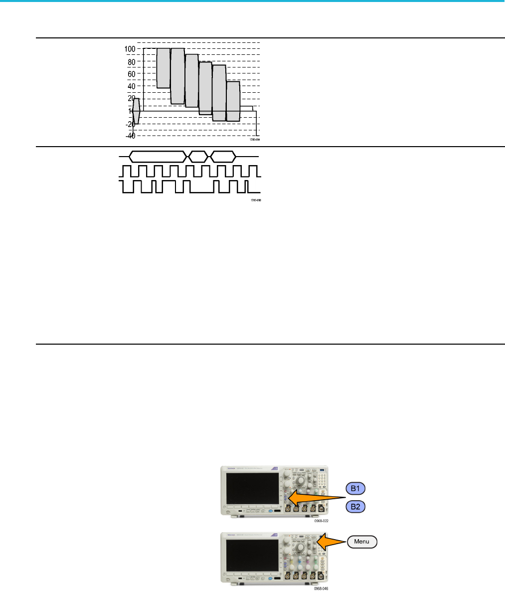
To set up the bus trigger:
1. If you have not already defined your bus
using the front panel B1 or B2 buttons, do
so now. (See page 67, Setting Up a Serial
or Parallel Bus.)
2. Push Trigger Menu.
MDO3000 Series Oscilloscopes User Manual 95