
User Manual
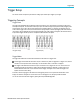
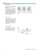
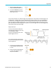
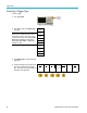
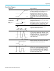
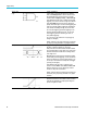
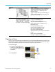
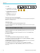
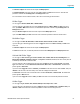
Table Of Contents
- toc
- Important safety information
- Compliance information
- Preface
- Installation
- Before Installation
- Operating Considerations
- Connecting Probes
- Securing the Oscilloscope
- Powering on the Oscilloscope
- Powering off the Oscilloscope
- Functional Check
- Compensating a TPP0250, TPP0500B or TPP1000 Passive Voltage Prob
- Compensating a non-TPP0250, non-TPP0500B or non-TPP1000 Passive
- Application Module Free Trial
- Installing an Application Module
- Upgrading Bandwidth
- Changing the Language of the User Interface or Keyboard
- Changing the Date and Time
- Signal Path Compensation
- Upgrading Firmware
- Connecting Your Oscilloscope to a Computer
- Connecting a USB Keyboard to Your Oscilloscope
- Get Acquainted with the Instrument
- Acquire the Signal
- Setting Up Analog Channels
- Using the Default Setup
- Using Autoset
- Acquisition Concepts
- Using FastAcq
- How the Analog Acquisition Modes Work
- Changing the Acquisition Mode, Record Length, and Delay Time
- Using Roll Mode
- Act on Event
- Setting Up a Serial or Parallel Bus
- Setting Up Digital Channels
- When and Why to Turn On MagniVu
- Using MagniVu
- Setting Up the RF Inputs
- Trigger Setup
- Display Waveform or Trace Data
- Adding and Removing a Waveform
- Setting the Display Style and Persistence
- Setting Waveform Intensity
- Scaling and Positioning a Waveform
- Setting Input Parameters
- Positioning and Labeling Bus Signals
- Positioning, Scaling, and Grouping Digital Channels
- Viewing Digital Channels
- Annotating the Screen
- Viewing the Trigger Frequency
- Displaying the Frequency Domain Menu
- Analyze Waveform or Trace Data
- Using Markers in the Frequency Domain
- Taking Automatic Measurements in the Time Domain
- Selecting Automatic Measurements in the Time Domain
- Customizing an Automatic Measurement in the Time Domain
- Taking Automatic Measurements in the Frequency Domain
- Taking Digital Voltmeter Measurements
- Taking Manual Measurements with Cursors
- Setting Up a Histogram
- Using Math Waveforms
- Using FFT
- Using Advanced Math
- Using Spectrum Math
- Using Reference Waveforms and Traces
- Using Wave Inspector to Manage Long Record Length Waveforms
- Auto-magnify
- Limit and Mask Testing
- Making Video Tests
- Making Automated Power Measurements
- Save and Recall Information
- Use the Arbitrary Function Generator
- Use the Application Modules
- Appendix A: Warranted Specifications
- Appendix B: TPP0250, TPP0500B and TPP1000: 250€MHz, 500€MHz and
- Appendix C: P6316 General-Purpose Logic Probe Information
- Appendix D: OpenSSL License
Trigger Setup
3. Push Type.
Type
Bus
Source
Bus
B1 (I2C)
Trigger On
Address
Address
07F
Direction
Write
Mode
Auto
& Holdoff
4. Turn Multipur
pose a to scroll through the
trigger type side menu until you select Bus.
5. Push Source Bus and use the Source Bus
side menu to
select the bus that you want
to trigger on.
6. Push Trigge
rOnand select the desired
trigger on feature from the side menu.
Parallel Bus Trigger (requires option MDO3MSO)
You can trigger on a binary or hex data value. Push Data on the lower menu and enter the parameters of interest with the
Multipurpose a and Multipu rpo se b knobs.
ARINC429 Bus Trigger
You can trigger on Word Start, Label, Data, Label and Data, Word End, and E rror.
If you have made a Trigger On selection of Label or Label and D a ta , push Lab el on the lower menu and enter a qualifier
and Lab
el values of interest.
NOTE. When the Trigger On selection is Label and Data, the qualifier for the Label value must be "EQUAL" and is locked
to this value. It is unlocked when the Trigger On conditions is changed.
If yo
u have m ade a Trigger On selection of Data or Label and Data, push Data on the lower menu and enter a qualifier
and Data values of interest.
If you have made a Trigger On selection of Error, push Error Type on the lower menu and select Any Error, Parity
Error, Word Error,orGap Error.
I
2
C
Bus Trigger
You can trigger on Start, Repeated Start, Stop, Missing Ack, Address, Data,orAddress/Data.
If you are setting up an I
2
C trigger and have made a Trigger On selection of Address or Address/Data, push Address
on the lower menu to access the I
2
C Address side menu.
Push Addressing Mode on the side menu and select 7bitor 10 bit .PushAddress on the side menu. Enter the address
parameters of interest with the Multipurpose a and Multipurpose b knobs.
Then push Direction on the lower menu and select the direction of interest: Read, Write,orRead or Write.
If you have made a Trigger On selection of Data or Address/Data, push Data on the lower menu to access the I
2
C
Data side menu.
96 MDO3000 Series Oscilloscopes User Manual