
User Manual
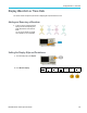
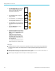
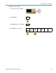
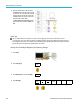
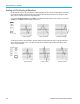
Table Of Contents
- toc
- Important safety information
- Compliance information
- Preface
- Installation
- Before Installation
- Operating Considerations
- Connecting Probes
- Securing the Oscilloscope
- Powering on the Oscilloscope
- Powering off the Oscilloscope
- Functional Check
- Compensating a TPP0250, TPP0500B or TPP1000 Passive Voltage Prob
- Compensating a non-TPP0250, non-TPP0500B or non-TPP1000 Passive
- Application Module Free Trial
- Installing an Application Module
- Upgrading Bandwidth
- Changing the Language of the User Interface or Keyboard
- Changing the Date and Time
- Signal Path Compensation
- Upgrading Firmware
- Connecting Your Oscilloscope to a Computer
- Connecting a USB Keyboard to Your Oscilloscope
- Get Acquainted with the Instrument
- Acquire the Signal
- Setting Up Analog Channels
- Using the Default Setup
- Using Autoset
- Acquisition Concepts
- Using FastAcq
- How the Analog Acquisition Modes Work
- Changing the Acquisition Mode, Record Length, and Delay Time
- Using Roll Mode
- Act on Event
- Setting Up a Serial or Parallel Bus
- Setting Up Digital Channels
- When and Why to Turn On MagniVu
- Using MagniVu
- Setting Up the RF Inputs
- Trigger Setup
- Display Waveform or Trace Data
- Adding and Removing a Waveform
- Setting the Display Style and Persistence
- Setting Waveform Intensity
- Scaling and Positioning a Waveform
- Setting Input Parameters
- Positioning and Labeling Bus Signals
- Positioning, Scaling, and Grouping Digital Channels
- Viewing Digital Channels
- Annotating the Screen
- Viewing the Trigger Frequency
- Displaying the Frequency Domain Menu
- Analyze Waveform or Trace Data
- Using Markers in the Frequency Domain
- Taking Automatic Measurements in the Time Domain
- Selecting Automatic Measurements in the Time Domain
- Customizing an Automatic Measurement in the Time Domain
- Taking Automatic Measurements in the Frequency Domain
- Taking Digital Voltmeter Measurements
- Taking Manual Measurements with Cursors
- Setting Up a Histogram
- Using Math Waveforms
- Using FFT
- Using Advanced Math
- Using Spectrum Math
- Using Reference Waveforms and Traces
- Using Wave Inspector to Manage Long Record Length Waveforms
- Auto-magnify
- Limit and Mask Testing
- Making Video Tests
- Making Automated Power Measurements
- Save and Recall Information
- Use the Arbitrary Function Generator
- Use the Application Modules
- Appendix A: Warranted Specifications
- Appendix B: TPP0250, TPP0500B and TPP1000: 250€MHz, 500€MHz and
- Appendix C: P6316 General-Purpose Logic Probe Information
- Appendix D: OpenSSL License

Trigger Setup
With USB, CAN, CAN FD, or FlexRay, obtain a rolling window match by setting the Byte Of fset in the Data menu to
Don't care.
Specific byte matching (non-rolling window matching for a specific position in the packet) for I
2
C, SPI,
USB, CAN, CAN FD, LIN, and FlexRay.
You c an trigger on a specificbyteforI
2
C, SPI, CAN, CAN FD, LIN, and FlexRay in several ways:
For I
2
C and SPI, enter the number of bytes to match the num ber of bytes in the signal. Then use don't cares (X) to
mask the bytes that you are not interested in.
For I
2
C, push Trigger On on the lower menu to trigger on Address/Data. Push Ad dress. On the side menu, push
Address,an
dturnMultipurpose a and Multipurpose b as needed. Set the address to don't cares (X) if you want to
mask the address. The data will be matched starting at the first byte without using a rolling window.
For USB, triggering occurs when the user-selected data input matches the data and qualifier in the signal starting at
the byte offset. Set the number of bytes to match the number of bytes of interest. Use the data qualifier to perform: =,
!=,<,>,>=
, and <= operations.
For CAN an
d CAN FD triggering o ccurs when the user-selected data input matches the data and qualifier in the signal
starting at the byte offset. Set the number of bytes to match the number of bytes of interest. Use the data qualifier to
perform: =, !=, <, >, >=, and <= operations. Triggering on identifier and data always performs an exact match on
the speci
fied identifier and uses the selected qualifier operation on the data, starting at the byte offset. Setting the
qualifier to perform an “=” comparison will allow matching o n up to 8 bytes of data. All other qualifiers are limited to
4 bytes of specified data.
For LIN, triggering occurs when the user-selected data input matches the data and qualifier in the signal starting with the
first dat
a byte. Set the number of bytes to match the number of bytes of interest. Use the data qualifier to perform: =, !=,
<, >, >=, <=, In Range, and Out of Range operations. Triggering on identifier and data always performs an exact match
on the specified identifier and uses the selected qualifi er operation on the data, starting with the first data byte. Setting
the qua
lifier to perform an “=” comparison will allow matching on up to 8 bytes of data. All other qualifiers are limited
to 4 bytes of specified data. No rolling window is used.
For FlexRay and Ethernet, triggering occurs when the user-selected data input matches the data and qualifier in the
signal starting at the byte offset. Set the number of bytes to match the number of bytes of interest. Use the data qualifier
to per
form: =, !=, <, >, >=, and <= operations. Triggering on identifier and data always m atches the identifier and data
selected by the user, with the data starting at the first byte. No rolling window is used.
Data Value Matching
You can trigger on a specific data value for RS-232 bytes. If you defined an end-of-packet character to use for RS-232 bus
decoding, you can use the same end-of-packet c haracter as a data value for trigger data matching. To do so, choose the Tx
End of Packet or the Rx End of Packet character as the Trigger On selection.
You can also trigger on a specific data value for other buses.
Parallel Bus Trigger Data Matching
Optimum parallel bus trigger performance is achieved by using only analog channels or only digital channels.
MDO3000 Series Oscilloscopes User Manual 99