
User Manual
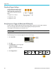
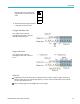
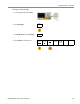
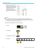
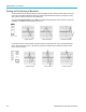
Table Of Contents
- toc
- Important safety information
- Compliance information
- Preface
- Installation
- Before Installation
- Operating Considerations
- Connecting Probes
- Securing the Oscilloscope
- Powering on the Oscilloscope
- Powering off the Oscilloscope
- Functional Check
- Compensating a TPP0250, TPP0500B or TPP1000 Passive Voltage Prob
- Compensating a non-TPP0250, non-TPP0500B or non-TPP1000 Passive
- Application Module Free Trial
- Installing an Application Module
- Upgrading Bandwidth
- Changing the Language of the User Interface or Keyboard
- Changing the Date and Time
- Signal Path Compensation
- Upgrading Firmware
- Connecting Your Oscilloscope to a Computer
- Connecting a USB Keyboard to Your Oscilloscope
- Get Acquainted with the Instrument
- Acquire the Signal
- Setting Up Analog Channels
- Using the Default Setup
- Using Autoset
- Acquisition Concepts
- Using FastAcq
- How the Analog Acquisition Modes Work
- Changing the Acquisition Mode, Record Length, and Delay Time
- Using Roll Mode
- Act on Event
- Setting Up a Serial or Parallel Bus
- Setting Up Digital Channels
- When and Why to Turn On MagniVu
- Using MagniVu
- Setting Up the RF Inputs
- Trigger Setup
- Display Waveform or Trace Data
- Adding and Removing a Waveform
- Setting the Display Style and Persistence
- Setting Waveform Intensity
- Scaling and Positioning a Waveform
- Setting Input Parameters
- Positioning and Labeling Bus Signals
- Positioning, Scaling, and Grouping Digital Channels
- Viewing Digital Channels
- Annotating the Screen
- Viewing the Trigger Frequency
- Displaying the Frequency Domain Menu
- Analyze Waveform or Trace Data
- Using Markers in the Frequency Domain
- Taking Automatic Measurements in the Time Domain
- Selecting Automatic Measurements in the Time Domain
- Customizing an Automatic Measurement in the Time Domain
- Taking Automatic Measurements in the Frequency Domain
- Taking Digital Voltmeter Measurements
- Taking Manual Measurements with Cursors
- Setting Up a Histogram
- Using Math Waveforms
- Using FFT
- Using Advanced Math
- Using Spectrum Math
- Using Reference Waveforms and Traces
- Using Wave Inspector to Manage Long Record Length Waveforms
- Auto-magnify
- Limit and Mask Testing
- Making Video Tests
- Making Automated Power Measurements
- Save and Recall Information
- Use the Arbitrary Function Generator
- Use the Application Modules
- Appendix A: Warranted Specifications
- Appendix B: TPP0250, TPP0500B and TPP1000: 250€MHz, 500€MHz and
- Appendix C: P6316 General-Purpose Logic Probe Information
- Appendix D: OpenSSL License

Trigger Setup
Checking Trigger Settings
To quickly det
ermine the settings of some
key trigger parameters, check the Trigger
readout at the bottom of the display. The
readouts d iff
er for edge and the advanced
triggers.
1. Trigger source = channel 1.
2. Trigger slope = rising.
3. Trigger level = 0.00 V.
Edge trigger readout
Using Sequence Trigger (A (Main) and B (Delayed))
Combine an edge A Event (Main) trigger with the B Event (Delayed) trigger to capture m ore complex signals. After the A
Event occurs, the trigger system looks for the B Event before triggering and displaying the waveform.
A and B triggers can (and typically do) have separate sources.
NOTE. You can select sequence triggering when you choose the slope type Falling or Rising — but not when you pick
the slope type Both.
Use the Edge trigger menu to set up the A trigger first. Then, to use the B trigger:
1. P ush Trigger Menu.
2. Push Type.
3. Turn Multipurpose a to select a trigger type
of Sequence (B Trigger).
This brings up the Sequence (B Trigger)
menu.
4. Push BTriggerAfterA.
Type
Sequence
(B Trigger)
Source
1
Coupling
DC
Slope
Level
0.00 V
B Trigger
After A
Time
Mode
Auto
& Holdoff
100 MDO3000 Series Oscilloscopes User Manual