
User Manual
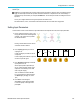
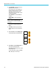
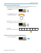
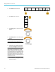
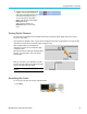
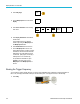
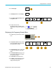
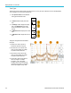
Table Of Contents
- toc
- Important safety information
- Compliance information
- Preface
- Installation
- Before Installation
- Operating Considerations
- Connecting Probes
- Securing the Oscilloscope
- Powering on the Oscilloscope
- Powering off the Oscilloscope
- Functional Check
- Compensating a TPP0250, TPP0500B or TPP1000 Passive Voltage Prob
- Compensating a non-TPP0250, non-TPP0500B or non-TPP1000 Passive
- Application Module Free Trial
- Installing an Application Module
- Upgrading Bandwidth
- Changing the Language of the User Interface or Keyboard
- Changing the Date and Time
- Signal Path Compensation
- Upgrading Firmware
- Connecting Your Oscilloscope to a Computer
- Connecting a USB Keyboard to Your Oscilloscope
- Get Acquainted with the Instrument
- Acquire the Signal
- Setting Up Analog Channels
- Using the Default Setup
- Using Autoset
- Acquisition Concepts
- Using FastAcq
- How the Analog Acquisition Modes Work
- Changing the Acquisition Mode, Record Length, and Delay Time
- Using Roll Mode
- Act on Event
- Setting Up a Serial or Parallel Bus
- Setting Up Digital Channels
- When and Why to Turn On MagniVu
- Using MagniVu
- Setting Up the RF Inputs
- Trigger Setup
- Display Waveform or Trace Data
- Adding and Removing a Waveform
- Setting the Display Style and Persistence
- Setting Waveform Intensity
- Scaling and Positioning a Waveform
- Setting Input Parameters
- Positioning and Labeling Bus Signals
- Positioning, Scaling, and Grouping Digital Channels
- Viewing Digital Channels
- Annotating the Screen
- Viewing the Trigger Frequency
- Displaying the Frequency Domain Menu
- Analyze Waveform or Trace Data
- Using Markers in the Frequency Domain
- Taking Automatic Measurements in the Time Domain
- Selecting Automatic Measurements in the Time Domain
- Customizing an Automatic Measurement in the Time Domain
- Taking Automatic Measurements in the Frequency Domain
- Taking Digital Voltmeter Measurements
- Taking Manual Measurements with Cursors
- Setting Up a Histogram
- Using Math Waveforms
- Using FFT
- Using Advanced Math
- Using Spectrum Math
- Using Reference Waveforms and Traces
- Using Wave Inspector to Manage Long Record Length Waveforms
- Auto-magnify
- Limit and Mask Testing
- Making Video Tests
- Making Automated Power Measurements
- Save and Recall Information
- Use the Arbitrary Function Generator
- Use the Application Modules
- Appendix A: Warranted Specifications
- Appendix B: TPP0250, TPP0500B and TPP1000: 250€MHz, 500€MHz and
- Appendix C: P6316 General-Purpose Logic Probe Information
- Appendix D: OpenSSL License

Display Wavefor
morTraceData
10. Select Probe Setup to define probe
parameters.
On the side men
u:
Select Voltag
e or Current to set the
probe type for probes that do not
have a TekProbe Level 1, TekProbe II
(requires a T
PA-BNC adapter) or TekVPI
interface.
For probes that do not have a Tek
interface, when Probe Type is set to
Voltage,tu
rn Multipurpose a to set
Attenuation to match the probe
For probes that do not have a Tek
interface, when Probe Type is set to
Current,t
urn M u ltipurpose a to set the
Amps/Volts ratio (Attenuation) to match
the probe.
If you are measuring current by probing
the voltage drop across a resistor,
set Meas
ure Current to Yes. Push
A/V ratio on the side menu and turn
Multipurpose a to set the Amps/Volts
or Volts
/Amp ratio of your setup. For
example, if you are measuring the drop
across a 2 resistor, s et the V/A ratio
to 2.
For som
e types of probes, you can push
this button to instruct the oscilloscope to
perform an AC calibration on the entire
signa
l path from the probe tip to the
specific oscilloscope channel. This can
result in a flatter frequency response
over t
he entire frequency range.
11. Select Deskew to make display and
meas
urement adjustments for probes that
have differing propagation delays. This is
especially important when using a current
pro
be in conjunction with a voltage probe.
For best results, use a deskew fixture, such
as the Tektronix 067-1686-xx.
MDO3000 Series Oscilloscopes User Manual 111