
User Manual
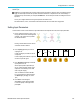
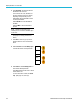
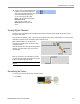
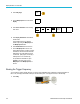
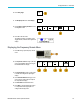
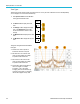
Table Of Contents
- toc
- Important safety information
- Compliance information
- Preface
- Installation
- Before Installation
- Operating Considerations
- Connecting Probes
- Securing the Oscilloscope
- Powering on the Oscilloscope
- Powering off the Oscilloscope
- Functional Check
- Compensating a TPP0250, TPP0500B or TPP1000 Passive Voltage Prob
- Compensating a non-TPP0250, non-TPP0500B or non-TPP1000 Passive
- Application Module Free Trial
- Installing an Application Module
- Upgrading Bandwidth
- Changing the Language of the User Interface or Keyboard
- Changing the Date and Time
- Signal Path Compensation
- Upgrading Firmware
- Connecting Your Oscilloscope to a Computer
- Connecting a USB Keyboard to Your Oscilloscope
- Get Acquainted with the Instrument
- Acquire the Signal
- Setting Up Analog Channels
- Using the Default Setup
- Using Autoset
- Acquisition Concepts
- Using FastAcq
- How the Analog Acquisition Modes Work
- Changing the Acquisition Mode, Record Length, and Delay Time
- Using Roll Mode
- Act on Event
- Setting Up a Serial or Parallel Bus
- Setting Up Digital Channels
- When and Why to Turn On MagniVu
- Using MagniVu
- Setting Up the RF Inputs
- Trigger Setup
- Display Waveform or Trace Data
- Adding and Removing a Waveform
- Setting the Display Style and Persistence
- Setting Waveform Intensity
- Scaling and Positioning a Waveform
- Setting Input Parameters
- Positioning and Labeling Bus Signals
- Positioning, Scaling, and Grouping Digital Channels
- Viewing Digital Channels
- Annotating the Screen
- Viewing the Trigger Frequency
- Displaying the Frequency Domain Menu
- Analyze Waveform or Trace Data
- Using Markers in the Frequency Domain
- Taking Automatic Measurements in the Time Domain
- Selecting Automatic Measurements in the Time Domain
- Customizing an Automatic Measurement in the Time Domain
- Taking Automatic Measurements in the Frequency Domain
- Taking Digital Voltmeter Measurements
- Taking Manual Measurements with Cursors
- Setting Up a Histogram
- Using Math Waveforms
- Using FFT
- Using Advanced Math
- Using Spectrum Math
- Using Reference Waveforms and Traces
- Using Wave Inspector to Manage Long Record Length Waveforms
- Auto-magnify
- Limit and Mask Testing
- Making Video Tests
- Making Automated Power Measurements
- Save and Recall Information
- Use the Arbitrary Function Generator
- Use the Application Modules
- Appendix A: Warranted Specifications
- Appendix B: TPP0250, TPP0500B and TPP1000: 250€MHz, 500€MHz and
- Appendix C: P6316 General-Purpose Logic Probe Information
- Appendix D: OpenSSL License

Display Wavefor
morTraceData
If you do not have a deskew fixture, you
can use the controls in the Deskew menu to
set the oscill
oscope's deskew parameters
to recommended values, based on the
nominal propagation delay of each probe.
The oscillos
cope automatically loads the
nominal propagation delay values of TekVPI
and TekProbe II (requires use of a TPA-BNC
adaptor) p ro
bes. For other common probes,
first push Select on the side menu, and
select the channel to which the probe is
attached. T
hen push Probe Model on the
side menu, and select the probe model. If
your probe is not in the list, set probe model
to Other,a
nd push Propagation Delay on
the side menu and dial in its propagation
delay with Multipurpose a.
To display
the recommended deskew values
calculated by the oscilloscope, set Show
rec. deskews on the side menu to Yes.
To set the
deskew values of each channel
to the recommended values, push Set all
deskews to recommended values on the
side men
u.
Quick T
ips
Using Probes with the TekProbe II and TekVPI Interfaces. When you attach a probe with the TekProbe II or the
TekVPI interface, the oscilloscope sets the channel sensitivity, coupling, and termination resistance automatically to
match the probe requirements. Tek Probe II probes require use of the TPA-BNC Adapter.
The Difference Between Vertical Position and Offset. Adjust the vertical position to place the waveforms where you
want to see them. The waveform baseline indicators indicate the zero Volts (or Amps) level for each waveform. If you
adjust the channel's Vertical Scale, the waveform expands or contracts around the waveform's baseline indicator.
When you use the Channel<x> > More >Offset > Vertical Offset control to move a waveform, the baseline indicator
no longer represents zero. Instead, it represents the level of the offset. If you adjust the channel's Vertical Scale, the
waveform expands or contracts around the waveform's baseline indicator.
50 Ω Protection. If you select 50 termination, the maximum vertical scale factor is limited to 1 V/div, ex cept that with a
10X probe the scale factor is 10 V. If you apply excessive input voltage, the oscilloscope automatically switches to 1
M termination to protect the i nternal 50 termination. For more details, refer to the specifica tions in the MDO3000
Series Oscilloscopes Technical Reference.
112 MDO3000 Series Oscilloscopes User Manual