
User Manual
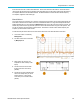
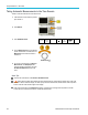
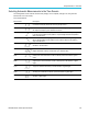
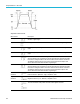
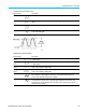
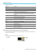
Table Of Contents
- toc
- Important safety information
- Compliance information
- Preface
- Installation
- Before Installation
- Operating Considerations
- Connecting Probes
- Securing the Oscilloscope
- Powering on the Oscilloscope
- Powering off the Oscilloscope
- Functional Check
- Compensating a TPP0250, TPP0500B or TPP1000 Passive Voltage Prob
- Compensating a non-TPP0250, non-TPP0500B or non-TPP1000 Passive
- Application Module Free Trial
- Installing an Application Module
- Upgrading Bandwidth
- Changing the Language of the User Interface or Keyboard
- Changing the Date and Time
- Signal Path Compensation
- Upgrading Firmware
- Connecting Your Oscilloscope to a Computer
- Connecting a USB Keyboard to Your Oscilloscope
- Get Acquainted with the Instrument
- Acquire the Signal
- Setting Up Analog Channels
- Using the Default Setup
- Using Autoset
- Acquisition Concepts
- Using FastAcq
- How the Analog Acquisition Modes Work
- Changing the Acquisition Mode, Record Length, and Delay Time
- Using Roll Mode
- Act on Event
- Setting Up a Serial or Parallel Bus
- Setting Up Digital Channels
- When and Why to Turn On MagniVu
- Using MagniVu
- Setting Up the RF Inputs
- Trigger Setup
- Display Waveform or Trace Data
- Adding and Removing a Waveform
- Setting the Display Style and Persistence
- Setting Waveform Intensity
- Scaling and Positioning a Waveform
- Setting Input Parameters
- Positioning and Labeling Bus Signals
- Positioning, Scaling, and Grouping Digital Channels
- Viewing Digital Channels
- Annotating the Screen
- Viewing the Trigger Frequency
- Displaying the Frequency Domain Menu
- Analyze Waveform or Trace Data
- Using Markers in the Frequency Domain
- Taking Automatic Measurements in the Time Domain
- Selecting Automatic Measurements in the Time Domain
- Customizing an Automatic Measurement in the Time Domain
- Taking Automatic Measurements in the Frequency Domain
- Taking Digital Voltmeter Measurements
- Taking Manual Measurements with Cursors
- Setting Up a Histogram
- Using Math Waveforms
- Using FFT
- Using Advanced Math
- Using Spectrum Math
- Using Reference Waveforms and Traces
- Using Wave Inspector to Manage Long Record Length Waveforms
- Auto-magnify
- Limit and Mask Testing
- Making Video Tests
- Making Automated Power Measurements
- Save and Recall Information
- Use the Arbitrary Function Generator
- Use the Application Modules
- Appendix A: Warranted Specifications
- Appendix B: TPP0250, TPP0500B and TPP1000: 250€MHz, 500€MHz and
- Appendix C: P6316 General-Purpose Logic Probe Information
- Appendix D: OpenSSL License
Analyze Wavefor
morTraceData
Amplitude measurements
Measurement Description
Peak-to-peak
The absolute difference between the maximum and minimum amplitude in the entire
waveform or gated region.
Amplitude
The high value less the low value m easured over the entire waveform or gated region.
Max
The most positive peak voltage. Max is measured over the entire w aveform or gated
region.
Min
The most negative peak voltage. Min is measured over the entire waveform or gated
region.
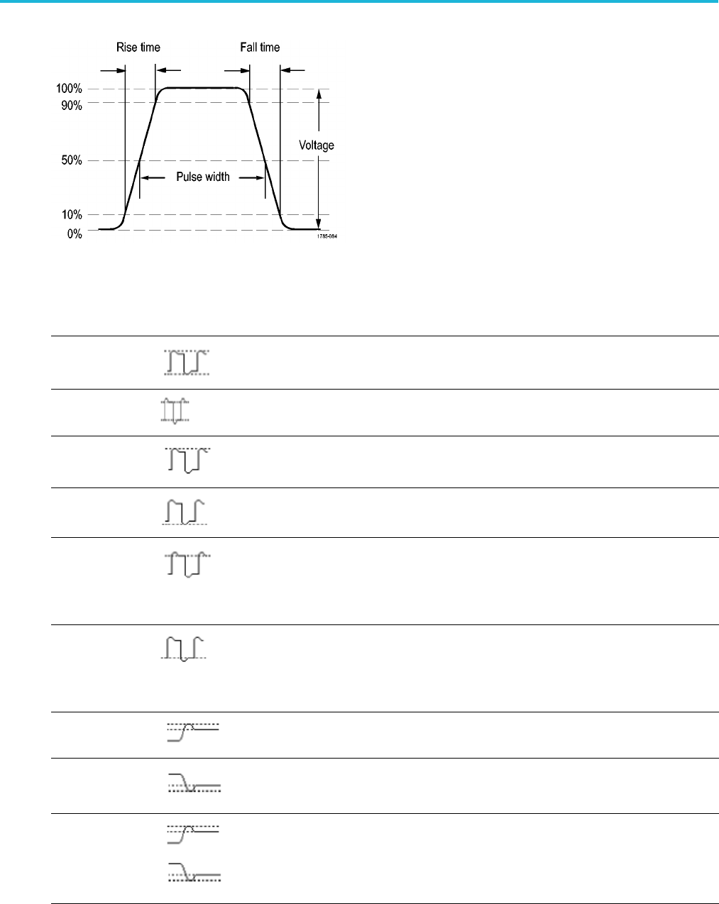
High
This value is used as 100% whenever high reference, mid reference, or low reference
values are needed, such as in fall time or rise time measurements. Calculate using either
the min/max or histogram method. The min/max method uses the maximum value found.
The histogram method uses the most common value found above the midpoint. This
value is measured over the entire w aveform or gated region.
Low
This value is used as 0% whenever high reference, mid reference, or low reference
values are needed, such as in fall time or rise time measurements. Calculate using either
the min/max or histogram method. The min/max method uses the minimum value found.
The histogram method uses the m ost common value found below the midpoint. This
value is measured over the entire w aveform or gated region.
Positive
Overshoot
This is measured over the entire waveform or gated region and is expressed as:
Positive Overshoot = (Maximum – High) / Amplitude x 100%.
Negative
Overshoot
This is measured over the entire waveform or gated region and is expressed as:
Negative Overshoot = (Low – Minimum) / Amplitude x 100% .
Total overshoot
This is the summation of the positive o vershoot and the negative overshoot.
126 MDO3000 Series Oscilloscopes User Manual